Table of Contents
Advertisement
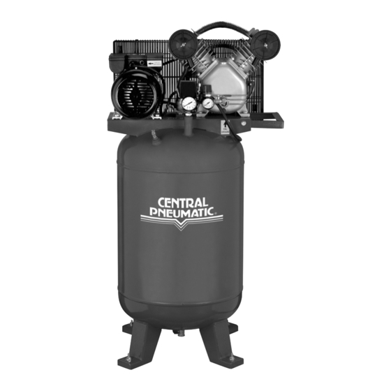
240 VOLT COMPRESSOR
4 HP PEAK – 29 GALLON
SET uP ANd OPERATiNG iNSTRuCTiONS
distributed exclusively by Harbor Freight Tools
Visit our website at: http://www.harborfreight.com
Read this material before using this product.
Failure to do so can result in serious injury.
SAVE THiS MANuAL.
Copyright
2008 by Harbor Freight Tools
©
contained herein may be reproduced in any shape or form without the express written consent of
Harbor Freight Tools. Diagrams within this manual may not be drawn proportionally. Due to continuing
improvements, actual product may differ slightly from the product described herein. Tools required for
assembly and service may not be included.
For technical questions or replacement parts, please call 1-800-444-3353.
Revised Manual 10g
3491 Mission Oaks Blvd., Camarillo, CA 93011
. All rights reserved. No portion of this manual or any artwork
®
65903
.
®
Advertisement
Table of Contents

Subscribe to Our Youtube Channel
Related Manuals for Central Pneumatic 65903


Summary of Contents for Central Pneumatic 65903
- Page 1 Tools required for assembly and service may not be included. For technical questions or replacement parts, please call 1-800-444-3353. Revised Manual 10g 65903 . All rights reserved. No portion of this manual or any artwork ® ®...
-
Page 2: Product Specifications
Keep your work area clean and well lit. accidents. For technical questions, please call 1-800-444-3353. SKU 65903 240 V~ / 60 Hz / 9 A (Load) / Single Phase / 4 HP Peak / 3 HP Working / 3,400 RPM / Two Capacitor (Run & Start) 15 A 12 Gauge, 3-Wire (Stripped), 10 Ft. -
Page 3: Electrical Safety
Keep proper footing and balance at all times. For technical questions, please call 1-800-444-3353. SKU 65903 ELECTRiCAL SAFETY Never use the Power Cord to pull the Plug NEVER bE uSEd WiTH THiS iTEM. Connecting... - Page 4 “Inspection, Maintenance, And Cleaning” section of this manual. Use of unauthorized parts or failure to follow maintenance instructions may create a risk of electric shock or injury. For technical questions, please call 1-800-444-3353. SKU 65903 TOOL uSE ANd CARE SERViCE Make sure you are wear-...
-
Page 5: Specific Safety Rules
SPECiFiC SAFETY RuLES CAuTiON! Prior to its make sure to fill the Air Compressor with a premium quality, 30 weight, non- detergent oil to the specified level. Running the Air Compressor with no oil or with low oil will cause damage to the equipment and void its warranty. Refer to the “Operating Instructions”... - Page 6 CuiT AS THE AMPERAGE dRAW uNdER FuLL LOAd, COMbiNEd WiTH uSE OF ANY OTHER iTEM, MAY OVERLOAd YOuR CiRCuiT. Always turn off the Air Compressor in the event of a power failure. Performance of this Air Compressor may vary depending on variations in lo- cal line voltage.
-
Page 7: Assembly Instructions
240 volt electrical outlet that is properly grounded. Prior to use, the Air Compressor requires the attachment of a 1/4” NPT Quick Connector (not included) to the Air Outlet Valve (4). To do so, wrap approximately 4” of pipe thread sealant tape (not included) around the male threads of the Quick Connector. - Page 8 Fill Cap (28) to remove. (See Figure d.) Once the Oil Fill Cap (28) is removed, fill the Air Compressor with a premium qual- ity, 30 weight, non-detergent oil until the level of the oil rises to the midway point in the Oil Level Indicator (35).
-
Page 9: Operating Instructions
Make sure to blow out the concrete dust from the drilled holes. Set the Air Compressor back to the location where it is to be used, and align the four 1/2” diameter mounting holes in its legs with the four pre-drilled 1/2” holes in the concrete or wood. -
Page 10: To Start The Air Compressor
To use The Overload Reset button: The Air Compressor is equipped with an internal electrical circuit breaker which is designed to automatically shut off the Air Compressor in the event its Motor (14) becomes overheated. (See Figure E.) Should the Air Compressor automatically shut off at a pressure less than 115 PSI, rotate the Power Switch Lever (9) down to its “OFF”... - Page 11 Switch Lever (9) to its “ON” position to resume work. (See Figure E.) To Turn Off The Air Compressor: When finished using the Air Compressor, press down on its Power Switch Lever (9) to turn off the unit. (See Figure E.) Disconnect the Power Cord Plug (31) from its electrical outlet.
-
Page 12: Inspection, Maintenance, And Cleaning
(41) FiGuRE F before each use: Make sure to fill the Air Compressor with a premium quality, 30 weight, non-detergent oil. Running the Air Compressor with no oil or low oil will cause damage to the equipment and void its warranty. When filling the Air Com- pressor with oil, make sure to unscrew (do not pull) the Oil Fill Cap (28) to remove. - Page 13 NuT (24) CLiP (23) To replace the V-belt: The Air Compressor is equipped with a V-Belt (size: A1118 Li). To replace the V-Belt, remove the five Nuts (24) and Clips (23) on the Outer Guard Screen (25). Then, remove the Outer Guard Screen.
- Page 14 If necessary move the Motor Pulley (14) toward or away from the Large Belt Wheel until the V-Belt deflects downward 3/4”. Then, retighten the four Screws (3) to se- cure the Motor (14) in place. (See Figures i and J.) For technical questions, please call 1-800-444-3353. SKU 65903 ENd ViEW SCREW SCREW...
-
Page 15: Limited 1 Year / 90 Day Warranty
When storing, make sure to keep the Air Compressor in a safe, clean, and dry location out of reach of children. CAuTiON! All maintenance, service, or repairs not listed in this manual are only to be attempted by a qualified service technician. -
Page 16: Please Read The Following Carefully
Note: If product has no serial number, record month and year of purchase instead. Note: Some parts are listed and shown for illustration purposes only, and are not avail- able individually as replacement parts. For technical questions, please call 1-800-444-3353. SKU 65903 PARTS LiST qty. Part... -
Page 17: Assembly Diagram
ASSEMbLY diAGRAM REV 10g For technical questions, please call 1-800-444-3353. SKU 65903 Page 17...
Need help?
Do you have a question about the 65903 and is the answer not in the manual?
Questions and answers