Table of Contents
Advertisement
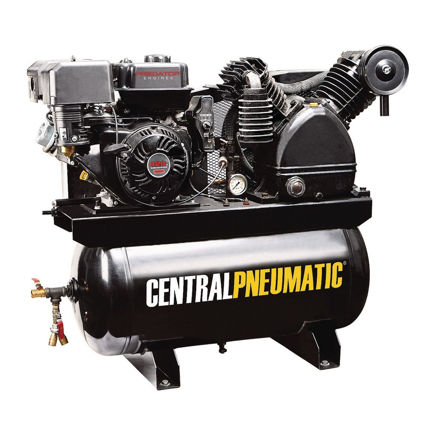
30 Gallon, 180 PSI
Gas Powered Two-Stage Air Compressor
67853 Air Compressor
Using an engine indoors CAN KILL YOU
IN MINUTES.
Engine exhaust contains carbon monoxide.
This is a poison you cannot see or smell.
NEVER use inside
a home or garage,
EVEN IF doors and
windows are open.
When unpacking, make sure that the product is intact and undamaged.
If any parts are missing or broken, please call 1-800-444-3353 as soon as possible.
Record Product's Serial Number Here:
Note: If product has no serial number, record month and year of purchase instead.
Note: Some parts are listed and shown for illustration purposes only, and are not available individually
as replacement parts.
©
Copyright
2010 by Harbor Freight Tools
or form without the express written consent of Harbor Freight Tools. Diagrams within this manual may not be drawn proportionally. Due to continuing
improvements, actual product may differ slightly from the product described herein. Tools required for assembly and service may not be included.
Manual Revised 11e
Only use OUTSIDE
and far away from
windows, doors,
and vents.
Visit our website at: http://www.harborfreight.com
Email our tech support at: tech@harborfreight.com
®
. All rights reserved. No portion of this manual or any artwork contained herein may be reproduced in any shape
Advertisement
Table of Contents
Troubleshooting

Related Manuals for Central Pneumatic Central Pneumatic 30 Gallon, 180 PSI Gas Powered Two-Stage Air Compressor


Summary of Contents for Central Pneumatic Central Pneumatic 30 Gallon, 180 PSI Gas Powered Two-Stage Air Compressor
- Page 1 . All rights reserved. No portion of this manual or any artwork contained herein may be reproduced in any shape or form without the express written consent of Harbor Freight Tools. Diagrams within this manual may not be drawn proportionally. Due to continuing improvements, actual product may differ slightly from the product described herein.
- Page 3 Save This Manual Symbol Definitions Keep this manual for the safety warnings and precautions, Symbol Property or Statement assembly, operating, inspection, maintenance and cleaning procedures. Write the product’s serial number in the Revolutions Per Minute back of the manual near the assembly diagram (or month and year of purchase if product has no number).
- Page 4 4. Set up and use only on a flat, level, 9. Do not leave the equipment unattended when it is well-ventilated surface. running. Turn off the equipment (and remove safety keys, if available) before leaving the work area. 5. Use only lubricants and fuel recommended in the engine manual or in the Specifications chart of 10.
-
Page 5: Air Compressor Safety Warnings
5. Maintain labels and nameplates on the equipment. recommended by the manufacturer may result in a risk These carry important information. If unreadable of injury to persons. or missing, contact Harbor Freight Tools for 11. All air line components, including hoses, pipe, a replacement. connectors, filters, etc., must be rated for a minimum ... - Page 6 Engine Controls Pump Safety Valve (91) Belt Guard Frame (121) & Pilot Valve Belt Guard Cover (129) Air Filter Assembly (84) ON/OFF Switch Sight Glass (19) Tank Pressure Gauge (97) Tank Safety Valve (98) Outlet (105) Drain Valve (137) Crankcase (16) 1.
- Page 7 Set up The emission control system for this Compressor’s Engine is warranted for standards set by the U.S. Environmental Protection Agency and by the California Air Resources Board (also known as CARB). For warranty information, refer to the engine manual. Mounting to a Truck bed 1.
- Page 8 Air Tool & Spray Gun Portable Setup Page 6 For technical questions, please call 1-800-444 3353. Item 67853...
- Page 9 Air Tool & Spray Gun Stationary Setup Item 67853 For technical questions, please call 1-800-444 3353. Page 7...
-
Page 10: Close The In-Line Shutoff Valve
Operation Read the ENTIRE IMPORTANT SAFETY INFORMATION section at the beginning of this manual including all text under subheadings therein before set up or use of this product. Using the Compressor Inspect Compressor, engine, pump and equipment looking for damaged, loose, and missing parts before set up and starting. If any problems are found, do not use equipment until fixed properly. - Page 11 5. To start a cold engine, move the Choke to the CHOKE (start/ closed) position. To restart a warm engine, leave the Choke in the RUN position. For MANUAL START For ELECTRIC START A. Turn the Engine Switch to ON. Turn the Engine Switch to START.
- Page 12 9. When the Gas Engine is started and running, the compressor Pump starts compressing air into the Air Tank. Open the in-line Shutoff Valve and adjust the Pressure Regulator (sold separately) so that the air output is enough to properly power the tool, but the output will not exceed the tool’s maximum air pressure at any time.
- Page 13 12. Close the in-line Shutoff Valve. 13. Bleed air from the tool then disconnect the tool. 14. Open the Drain Valve at the bottom of the Tank, to release any built-up moisture and the internal tank pressure. 15. Clean, then store the Air Compressor indoors. Item 67853 For technical questions, please call 1-800-444 3353.
-
Page 14: Maintenance Procedures
Heavy operation may require heavier viscosity oil. 3. If uncertain which oil to use for this compressor, please call Harbor Freight Tools customer service at 1-800-444-3353 for assistance. WARNING! To prevent serious injury from burns: Do not add or change the oil while the compressor is in operation. -
Page 15: Changing Oil
Maintenance Changing Oil Adjusting belt Tension 1. Remove the Belt Guard Cover (129) and set it aside. To drain the oil from the Pump Crankcase: Deflection a. Place a container under the Drain Plug. Distance b. Remove the Oil Plug to allow air flow into the Pump. c. Remove the Drain Plug, allowing the oil to drain into the container. - Page 16 Troubleshooting Problem Possible Causes Likely Solutions Engine will COMPRESSOR SPECIFIC: COMPRESSOR SPECIFIC: not start 1. Pilot Valve closed. 1. Open pilot valve before start procedure, close after unit is running. (Note: See engine 2. Tank already pressurized. 2. Turn engine on. Compressor will turn on as needed when manual for engine pressure reaches preset level.
- Page 17 PLEASE READ THE FOLLOWING CAREFULLY THE MANUFACTURER AND/OR DISTRIBUTOR HAS PROVIDED THE PARTS LIST AND ASSEMBLy DIAGRAM IN THIS MANUAL AS A REFERENCE TOOL ONLy. NEITHER THE MANUFACTURER OR DISTRIBUTOR MAKES ANy REPRESENTATION OR WARRANTy OF ANy KIND TO THE BUyER THAT HE OR SHE IS QUALIFIED TO MAKE ANy REPAIRS TO THE PRODUCT, OR THAT HE OR SHE IS QUALIFIED TO REPLACE ANy PARTS OF THE PRODUCT.
-
Page 18: Table Of Contents
Pump Parts List Part Description Part Description Bolt M12×55 Brass Tube Spring Washer 12 Cylinder Head Flat Washer Spring Washer Drive Pulley Bolt M10×65 Oil Seal Circle Bolt M8×60 Flange Plate Spring Washer 10 O-ring φ85 Bearing Elbow Bolt M12×40 Bolt M8×35 Oil Breather Spring Washer 8 Crank Case End Cover... - Page 19 Pump Assembly Diagram Item 67853 For technical questions, please call 1-800-444 3353. Page 17...
-
Page 20: Spring Washer 12 1
Tank Parts List Part Description Part Description Tank Bracket Connector Threaded Rod Pressure Gauge Bolt M6×20 Tank Safety Valve Belt Guard Bracket A Unloader Valve Belt Guard Frame Throttle Control Belt Connector Driven Pulley Taper Sleeve Pipe Nut Bushing Brass Tube Spring Washer 8 Air Outlet Bolt M8×30... - Page 21 Tank Assembly Diagram Item 67853 For technical questions, please call 1-800-444 3353. Page 19...
- Page 22 Limited 90 Day Warranty Harbor Freight Tools Co. makes every effort to assure that its products meet high quality and durability standards, and warrants to the original purchaser that this product is free from defects in materials and workmanship for the period of 90 days from the date of purchase.
- Page 23 Specifications Pump Two stage Air Outlet Size 1/2”- NPT female Auto Shut-Off @ 180 PSI Air Pressure Restart @ 140 PSI Air Tank Capacity 30 Gallons 18 SCFM @ 90 PSI Air Flow Capacity 19.5 SCFM @ 40 PSI Oil Capacity 61 oz.
- Page 24 . All rights reserved. No portion of this manual or any artwork contained herein may be reproduced in any shape or form without the express written consent of Harbor Freight Tools. Diagrams within this manual may not be drawn proportionally. Due to continuing improvements, actual product may differ slightly from the product described herein.
- Page 25 Specifications Description 68120, 68121 68136 68306 Displacement 212cc 346cc 420cc Engine Type Horizontal Single Cylinder 4 stroke OHV Cooling System Forced air cooled Type 87+ octane unleaded gasoline Fuel Capacity 1 Gallon 1 Gallon 1 Gallon 10W-30 above 32° F Type SAE 5W30 at 32°...
- Page 26 Save This Manual Symbol Definitions Keep this manual for the safety warnings and precautions, Symbol Property or Statement assembly, operating, inspection, maintenance and cleaning procedures. Write the product’s serial Revolutions Per Minute number in the back of the manual near the assembly diagram (or month and year of purchase if product Horsepower has no number).
-
Page 27: Bearing
Set up Precautions 6. Never store fuel or other flammable materials near the engine. 1. Gasoline fuel and fumes are flammable, and 7. Only use a suitable means of transport and potentially explosive. Use proper fuel storage lifting devices with sufficient weight bearing and handling procedures. - Page 28 23. Use the equipment, accessories, etc., in accordance 4. Wear ANSI-approved safety goggles, heavy-duty work with these instructions and in the manner intended for gloves, and dust mask/respirator during service. the particular type of equipment, taking into account 5. Maintain labels and nameplates on the the working conditions and the work to be performed.
- Page 29 Engine Controls Fuel Cap Air Filter Engine Switch (Electric Start Models) Starter Handle Muffler Oil Drain Plug Dipstick Throttle Starter Choke Serial Fuel Valve Number Location (Write on front cover of manual.) Engine Switch (Manual Start Models) Page 6 For Engine technical questions, please call 1-800-520-0882. Horizontal Engines...
- Page 30 Battery Setup Instructions Set Up 1. Place a fully charged, lead-acid 12 V, 36+ Ah battery (not included) in a stable, flat location near the engine. Model 68120: The emission control system for this 2. Only use cables sized to match their length engine is warranted for standards set by the U.S.
- Page 31 Checking and Filling Fuel Operation WARNING! TO PREVENT SERIOUS INJURY FROM FIRE: Read the ENTIRE IMPORTANT SAFETY Fill the fuel tank in a well-ventilated area away INFORMATION section at the beginning from ignition sources. If the engine is hot from of this manual including all text use, shut the engine off and wait for it to cool under subheadings therein before...
- Page 32 Manual Start 1. To start a cold engine, move the Choke to the CHOKE position. To restart a warm engine, leave the Choke in the RUN position. CHOKE 2. Open the Fuel Valve. 3. Slide the Throttle or Speed Control Lever to 1/3 away from the SLOW position (the “turtle”).
- Page 33 6. Allow the Engine to run for several seconds. Then, if the Choke lever is in the CHOKE position, move the Choke Lever very slowly to its RUN position. NOTE: Moving the Choke Lever too fast could stall the engine. CHOKE IMPORTANT: Allow the engine to run at no load for five minutes with no load after each start-up so that the engine can stabilize.
- Page 34 Electric Start (if equipped) 1. To start a cold engine, move the Choke to the CHOKE position. To restart a warm engine, leave the Choke in the RUN position. CHOKE 2. Open the Fuel Valve. 3. Slide the Throttle or Speed Control Lever to 1/3 away from the SLOW position (the “turtle”).
- Page 35 5. Allow the Engine to run for several seconds. Then, if the Choke lever is in the CHOKE position, move the Choke Lever very slowly to its RUN position. NOTE: Moving the Choke Lever too fast could stall the engine. CHOKE IMPORTANT: Allow the engine to run at no load for five minutes with no load after each start-up so that the engine can stabilize.
- Page 36 Service WARNING TO PREVENT SERIOUS INJURY FROM ACCIDENTAL STARTING: Turn the Power Switch of the equipment to its “OFF” position, wait for the engine to cool, and disconnect the spark plug cap before performing any inspection, maintenance, or cleaning procedures. TO PREVENT SERIOUS INJURY FROM EQUIPMENT FAILURE: Do not use damaged equipment.
- Page 37 Checking and Filling Fuel WARNING! TO PREVENT SERIOUS INJURY FROM FIRE: Fill the fuel tank in a well-ventilated area away Full level Full level from ignition sources. If the engine is hot from use, shut the engine off and wait for it to cool before adding fuel.
- Page 38 Spark Plug Maintenance 2. FUEL: WARNING! TO PREVENT SERIOUS INJURY FROM FIRE: Spark Drain the fuel tank in a well-ventilated area Plug away from ignition sources. If the engine is hot from use, shut the engine off and wait for it to cool before draining fuel.
-
Page 39: Troubleshooting
Troubleshooting Problem Possible Causes Probable Solutions Engine will not start FUEL RELATED: FUEL RELATED: 1. No fuel in tank or fuel valve closed. 1. Fill fuel tank and open fuel valve. 2. Choke not in CHOKE position, cold engine. 2. Move Choke to CHOKE position. 3. - Page 40 Problem Possible Causes Probable Solutions Engine misfires 1. Spark plug cap loose. 1. Check wire connections. 2. Incorrect spark plug gap or 2. Re-gap or replace spark plug. damaged spark plug. 3. Defective spark plug cap. 3. Replace spark plug cap. 4.
-
Page 41: Limited 90 Day Warranty
The United States Environmental Protection Agency (herein EPA) its products meet high quality and durability standards, and Harbor Freight Tools (herein HFT) are pleased to explain the emission and warrants to the original purchaser that this product control system warranty on your 1997 and later Small Off-Road Engine (herein engine). - Page 42 If you have any questions regarding your warranty rights and to the effect of “repair or replace as necessary” are warranted for responsibilities, you should contact the Harbor Freight Tools Customer the warranty period. Any warranted part which is scheduled for Service Department at 1-800-520-0882.
-
Page 43: Crankshaft 1
68120 212cc Parts List and Diagram Part Description Qty. Part Description Qty. Gasket, Cylinder Head Rocker, Valve Cover Asm., Cylinder Head Nut_ Valve Adjusting Gasket, Cylinder Head Cover Nut, Valve Lock Tube, Breather Spring, Valve Bolt Starter Asm., Recoil Stud Bolt Stud Shroud... - Page 44 68120 212cc Parts List and Diagram For Engine technical questions, please call 1-800-520-0882. Page 21 Horizontal Engines...
- Page 45 68121 212cc Parts List and Diagram Part Description Qty. Part Description Qty. Gasket, Cylinder Head Starter Asm., Recoil Cover Asm., Cylinder Head Bolt Gasket, Cylinder Head Cover Shroud Tube, Breather Shroud, Cylinder Body Bolt Shield,Lower Stud Protector, Oil Stud Switch Asm., Stop Engine Stud Bolt Bolt...
- Page 46 68121 212cc Parts List and Diagram For Engine technical questions, please call 1-800-520-0882. Page 23 Horizontal Engines...
- Page 47 68136 346cc Parts List and Diagram Part Description Qty. Part Description Qty. Gasket, Cylinder Head Plate Asm., Lifter Stopper Cover Asm., Cylinder Head Bolt, Valve Adjusting Gasket, Cylinder Head Cover Rocker, Valve Tube, Breather Nut, Valve Adjusting Bolt Asm., Cylinder Head Cover Nut, Valve Lock Stud Spring, Valve...
- Page 48 68136 346cc Parts List and Diagram For Engine technical questions, please call 1-800-520-0882. Page 25 Horizontal Engines...
- Page 49 68306 420cc Parts List and Diagram Part Description Qty. Part Description Qty. Gasket, Cylinder Head Spring, Valve Cover Asm., Cylinder Head Retainer, Valve Spring Gasket, Cylinder Head Cover Starter Asm., Recoil Tube, Breather Bolt Bolt Asm., Cylinder Head Cover Shroud Stud Shroud, Cylinder Body Stud...
- Page 50 68306 420cc Parts List and Diagram For Engine technical questions, please call 1-800-520-0882. Page 27 Horizontal Engines...
-
Page 51: Item
Mounting Hole Diagrams Note: Not to scale. ITEM 68120 / 68121 212cc 6.38 in. / 162mm 2.6 in. / 66mm ITEM 68136 346cc and ITEM 68306 420cc 7.72 in. / 196mm 4.13 in. / 105mm Page 28 For Engine technical questions, please call 1-800-520-0882. Horizontal Engines... - Page 52 Power Take-Off Diagrams Note: Not to scale. ITEM 68120 / 68121 212cc 2.43 in. / 61.7mm 5/16-24UNF 1.79 in. / 45.5mm 0.67 in. / 17mm 0.1875 in. / 4.78mm Ø0.75 in. / 19.05mm Ø3.625 in. / 92mm 4x5/16-24UNF ITEM 68136 346cc and ITEM 68306 420cc Ø3.625 in.
- Page 53 3491 Mission Oaks Blvd. • PO Box 6009 • Camarillo, CA 93011 • (800) 520-0882 www.harborfreight.com...
Need help?
Do you have a question about the Central Pneumatic 30 Gallon, 180 PSI Gas Powered Two-Stage Air Compressor and is the answer not in the manual?
Questions and answers
where do I purchase parts for my Central Pneumatic 30 gallon compressor
Were can you buy the parts