Table of Contents

Related Manuals for GORMAN-RUPP PUMPS SUPER T T6A60S-4045T Series


Summary of Contents for GORMAN-RUPP PUMPS SUPER T T6A60S-4045T Series
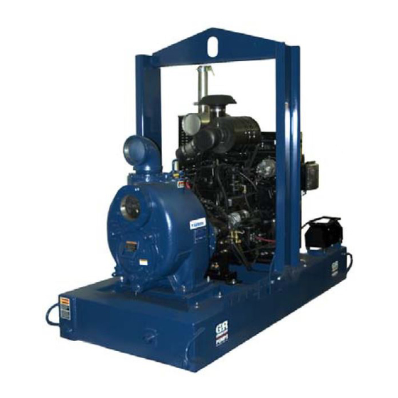
- Page 1 OM-06845-01 October 28, 2016 Rev. A - 03/08/19 INSTALLATION, OPERATION, AND MAINTENANCE MANUAL WITH PARTS LIST SUPER T SERIESr PUMP MODEL T6A60S-4045T FT4 GORMAN‐RUPP PUMPS www.grpumps.com 2016 Gorman‐Rupp Pumps Printed in U.S.A.
- Page 2 Register your new Gorman‐Rupp pump online at www.grpumps.com Valid serial number and e‐mail address required. The engine exhaust from this product contains chemicals known to the State of California to cause cancer, birth defects or other reproductive harm. RECORD YOUR PUMP MODEL AND SERIAL NUMBER Please record your pump model and serial number in the spaces provided below.
-
Page 3: Table Of Contents
TABLE OF CONTENTS INTRODUCTION ..........PAGE I - 1 SAFETY ‐... - Page 4 TABLE OF CONTENTS (continued) Automatic Stopping ........... . PAGE C - 4 Safety Shutdown System .
-
Page 5: Introduction
SUPER T SERIES OM-06845 INTRODUCTION Thank You for purchasing a Gorman‐Rupp pump. HAZARD AND INSTRUCTION Read this manual carefully to learn how to safely DEFINITIONS install and operate your pump. Failure to do so could result in personal injury or damage to the The following are used to alert maintenance per... -
Page 6: Safety - Section A
SUPER T SERIES OM-06845 SAFETY ‐ SECTION A This information applies to Super T Se forming any maintenance. Failure to do riesr engine driven pumps. Refer to the so may result in serious personal injury. manual accompanying the engine be fore attempting to begin operation. - Page 7 OM-06845 SUPER T SERIES deteriorate, and the liquid could come monoxide, a deadly gas that is color to a boil, build pressure, and cause the less, tasteless, and odorless. pump casing to rupture or explode. Fuel used by internal combustion en Do not remove plates, covers, gauges, gines presents an extreme explosion pipe plugs, or fittings from an over...
-
Page 8: Installation - Section B
SUPER T SERIES OM-06845 INSTALLATION - SECTION B Review all SAFETY information in Section A. specific application. Since the pressure supplied to the pump is critical to performance and safety, Since pump installations are seldom identical, this be sure to limit the incoming pressure to 50% of the section offers only general recommendations and maximum permissible operating pressure as practices required to inspect, position, and ar... -
Page 9: Battery Specifications And Installation
OM-06845 SUPER T SERIES ing, check for loose hardware at mating sur sion. Connect and tighten the positive cable first, faces. then the negative cable. c. Carefully read all tags, decals, and markings POSITIONING PUMP on the pump assembly, and perform all duties indicated. -
Page 10: Clearance
SUPER T SERIES OM-06845 tion. The pump and engine may be positioned up and increased shaft and seal wear. If hose‐type to 30 off horizontal for intermittent operation lines are used, they should have adequate support only; however, the engine manufacturer should be to secure them when filled with liquid and under consulted for continuous operation at angles pressure. -
Page 11: Sealing
OM-06845 SUPER T SERIES This pump is designed to handle up to 3‐inch (76,2 suction inlet at a distance 1‐1/2 times the diameter mm) diameter spherical solids. of the suction pipe. The baffle will allow entrained air to escape from the liquid before it is drawn into the suction inlet. -
Page 12: Float Switches
SUPER T SERIES OM-06845 Figure 2. Recommended Minimum Suction Line Submergence vs. Velocity FLOAT SWITCHES above the point where it bends along the bot tom. Direct the suction line toward the flow, and the float(s) away from the flow. If a stand Installation pipe is available, attach the float switch cable to the standpipe in the sump at the approxi... -
Page 13: Optional Submersible Transducer
OM-06845 SUPER T SERIES ENGINE (0.9) CONTROL (.76) (Emptying) (0.6) (Filling) (.46) OPERATING (0.3) RANGE CABLE (See Table Below) TETHER (.15) POINT (Emptying) (0.3) (0.6) (0.9) (1.2) APPROXIMATE FREE CORD LENGTH IN FT. (M) 1.25” Pipe (Filling) (Not Furnished) Figure 3. Float Switch Data OPTIONAL SUBMERSIBLE above the point where it bends along the bot... -
Page 14: Discharge Lines
SUPER T SERIES OM-06845 SUCTION LINE DISCHARGE LINE SIGNAL CABLE (ATTACH TO SUCTION LINE) SUCTION SUBMERSIBLE STRAINER TRANSDUCER (DOWNSTREAM FROM SUCTION) FLOW Figure 4. Typical Submersible Transducer Installation DISCHARGE LINES Siphoning If the application involves a high discharge head, gradually close the discharge Do not terminate the discharge line at a level lower throttling valve before stopping the pump. -
Page 15: Automatic Air Release Valve
OM-06845 SUPER T SERIES affect pump discharge capacity; however, the by stalled anywhere in a bypass line, it must pass line should be at least 1 inch (25,4 mm) in di be a full‐opening, ball‐type valve to pre ameter to minimize the chance of plugging. vent plugging by solids. -
Page 16: Air Release Valve Installation
SUPER T SERIES OM-06845 Air Release Valve Installation tween the pump discharge port and the inlet side of the discharge check valve (see Figure 5). The inlet The Automatic Air Release Valve must be inde opening in the Air Release Valve is equipped with pendently mounted in a horizontal position be... -
Page 17: Operation - Section C
OM-06845 SUPER T SERIES OPERATION - SECTION C OPERATION Review all SAFETY information in Section A. Make sure the pump is level. Lower jack Follow the instructions on all tags, labels and stands and chock the wheels, if so decals attached to the pump. equipped. -
Page 18: Routine Operation
OM-06845 SUPER T SERIES Add liquid to the pump casing when: continuous operating speed for this pump. 1. The pump is being put into service for the first time. A Gorman‐Rupp automatic air release valve may 2. The pump has not been used for a consider be installed in a bypass line, or the bypass line may able length of time. -
Page 19: Operation In Extreme Heat
OM-06845 SUPER T SERIES the source of the leak, check the point of installa OPERATION IN EXTREME HEAT tion of the vacuum gauge. The safety shutdown system will automatically Liquid Temperature And Overheating stop the unit if engine operating temperature ex ceeds design limits. -
Page 20: Stopping
OM-06845 SUPER T SERIES STOPPING shutdown before putting the unit back into service. Consult the factory for ad ditional information. Manual Stopping PERIODIC CHECKS In the manual mode, reduce the throttle speed slowly, and allow the engine to idle briefly before Seal Cavity and Bearing Lubrication turning the keyswitch to `OFF'. - Page 21 OM-06845 SUPER T SERIES Consult the manual accompanying the engine, for approximately one minute; this will remove any and change the oil filter periodically as indicated. If remaining liquid that could freeze the pump rotat operated under extremely dusty conditions, ing parts.
- Page 22 SUPER T SERIES OM-06845 TROUBLESHOOTING - SECTION D Review all SAFETY information in Section A. 5. Close the suction and discharge valves. 6. Vent the pump slowly and cau tiously. 7. Drain the pump. Before attempting to open or service the pump: 1.
- Page 23 OM-06845 SUPER T SERIES Table 1. Trouble Shooting Chart (cont.) TROUBLE POSSIBLE CAUSE PROBABLE REMEDY PUMP STOPS OR FAILS Leaking or worn seal or pump gas Check pump vacuum. Replace ket. leaking or worn seal or gasket. TO DELIVER RATED FLOW OR PRESSURE Strainer clogged.
- Page 24 SUPER T SERIES OM-06845 Table 1. Trouble Shooting Chart (cont.) TROUBLE POSSIBLE CAUSE PROBABLE REMEDY BEARINGS RUN TOO Bearing temperature is high, but Check bearing temperature regular within limits. ly to monitor any increase. Low or incorrect lubricant. Check for proper type and level of lubricant.
- Page 25 OM-06845 SUPER T SERIES Preventive Maintenance Schedule Service Interval* Item Daily Weekly Monthly Semi‐ Annually Annually General Condition (Temperature, Unusual Noises or Vibrations, Cracks, Leaks, Loose Hardware, Etc.) Pump Performance (Gauges, Speed, Flow) Bearing Lubrication Seal Lubrication (And Packing Adjustment, If So Equipped) V‐Belts (If So Equipped) Air Release Valve Plunger Rod (If So Equipped)
- Page 26 SUPER T SERIES OM-06845 PUMP MAINTENANCE AND REPAIR ‐ SECTION E MAINTENANCE AND REPAIR OF THE WEARING PARTS OF THE PUMP WILL MAINTAIN PEAK OPERATING PERFORMANCE. STANDARD PERFORMANCE FOR PUMP MODEL T6A60S-4045T FT4 Based on 70 F (21 C) clear water at sea level Contact the Gorman‐Rupp Company to verify per...
- Page 27 OM-06845 SUPER T SERIES ILLUSTRATION PARTS PAGE Figure 1. Pump Model T6A60S-4045T FT4 PAGE E - 2 MAINTENANCE & REPAIR...
- Page 28 SUPER T SERIES OM-06845 PARTS LIST Pump Model T6A60S-4045T FT4 (From S/N 1621414 Up) If your pump serial number is followed by an “N”, your pump is NOT a standard production model. Contact the Gorman‐Rupp Company to verify part numbers. ITEM PART PART NAME...
- Page 29 OM-06845 SUPER T SERIES ILLUSTRATION DETAIL A 16 15 Figure 2. Power Unit Kit PAGE E - 4 MAINTENANCE & REPAIR...
- Page 30 SUPER T SERIES OM-06845 PARTS LIST Power Unit Kit ITEM PART PART NAME NUMBER BASE/FUEL TANK ASSEMBLY 41553-053 24150 JOHN DEERE 4045T FT4 ENGINE 29224-471 CONTROL PANEL INSTALLATION KIT 48122-563 LIFTING BAIL KIT 48274-811 LOCK WASHER J10 15991 HEX NUT D10 15991 FLAT WASHER K10 15991...
- Page 31 OM-06845 SUPER T SERIES ILLUSTRATION Figure 3. Pump End Assembly PAGE E - 6 MAINTENANCE & REPAIR...
- Page 32 SUPER T SERIES OM-06845 PARTS LIST Pump End Assembly ITEM PART NAME PART ITEM PART NAME PART NUMBER NUMBER PUMP CASING SEE NOTE BELOW ADJUSTING SCREW 31871-070 1500G REPAIR ROTATING ASSY 44163-349 BACK COVER NUT 31871-073 15000 PIPE PLUG P04 15079 STUD C1213 15991 HEX HEAD CAP SCREW...
- Page 33 OM-06845 SUPER T SERIES ILLUSTRATION REPAIR ROTATING ASSEMBLY (REF) Figure 4. Repair Rotating Assembly PAGE E - 8 MAINTENANCE & REPAIR...
- Page 34 SUPER T SERIES OM-06845 PARTS LIST Repair Rotating Assembly ITEM PART PART NAME NUMBER IMPELLER 38615-087 11010 CTG SEAL ASSY 46513-154 SEAL PLATE 38272-254 10010 OIL SEAL S1917 GASKET 10959G 20000 LOCK WASHER J08 15991 HEX HEAD CAP SCREW B0805-1/2 15991 BEARING HOUSING 38251-517 10000 VENTED PIPE PLUG...
- Page 35 OM-06845 SUPER T SERIES ILLUSTRATION MODEL T6A60S LOCATE COUPLING AS DIMENSIONED Figure 5. Drive Assembly PARTS LIST ITEM PART PART NAME NUMBER COUPLING KIT 48112-001 -BUSHING 24131-345 -COUPLING ASSEMBLY 44165-011 -LOCKWASHER J06 15991 -LOCKWASHER 21171-536 -SOCKET HD CAPSCREW BD0606-1/2 15991 -SOCKET HD CAPSCREW 22644-220 HEX HD CAPSCREW...
- Page 36 SUPER T SERIES OM-06845 PUMP AND SEAL DISASSEMBLY manual are performed only after estab lishing that neither personal safety nor AND REASSEMBLY pump integrity are compromised by such practices. Review all SAFETY information in Section A. Follow the instructions on all tags, label and de cals attached to the pump.
- Page 37 OM-06845 SUPER T SERIES Suction Check Valve Removal (Figure 3) If the check valve assembly (30) is to be serviced, Use Only Genuine Gorman-Rupp re remove the check valve pin (32), reach through the placement parts. Failure to do so may cre back cover opening and pull the complete assem...
- Page 38 SUPER T SERIES OM-06845 It is not necessary to remove the outer ring of the Turn coupling from the engine flywheel unless the cou Counterclockwise pling must be replaced. To remove the ring, disen gage the hardware (4 and 5) securing it to the fly wheel.
- Page 39 OM-06845 SUPER T SERIES 7) and separate the seal plate (3) and gasket (5) from the bearing housing (8). Position the seal plate on a flat surface with the impeller side down. Use a wooden dowel or other suitable tool to press on the back side of the stationary seat until the APPROX.
- Page 40 SUPER T SERIES OM-06845 Shaft and Bearing Reassembly and Installation be cleaned and inspected in place. It is strongly recommended that the bearings (Figure 4) be replaced any time the shaft and bear ings are removed. Clean the bearing housing, shaft and all compo nent parts (except the bearings) with a soft cloth soaked in cleaning solvent.
- Page 41 OM-06845 SUPER T SERIES NOTE If a hot oil bath is used to heat the bearings, both the oil and the container must be absolutely clean. If the oil has been previously used, it must be thor When installing the shaft and bearings into oughly filtered.
- Page 42 SUPER T SERIES OM-06845 sleeve O‐ring (14) and the external stationary seat Reusing an old seal could result in prema O‐ring with a very small amount of light lubricating ture failure. oil. See Figure 8 for seal part identification. To ease installation of the seal, lubricate the shaft RETAINER SEAL PLATE SPRING...
- Page 43 OM-06845 SUPER T SERIES and screw the impeller onto the shaft until it is seat proper clearance as described in Impeller Instal ed against the seal (see Figure 9). lation and Adjustment. Continue to screw the impeller onto the shaft. This If necessary to reuse an old seal in an emergen...
- Page 44 SUPER T SERIES OM-06845 Slide the rotating portion of the seal (consisting of Rotating Assembly Installation the integral shaft sleeve, spring centering washer, (Figure 3) spring, bellows and retainer, and rotating element) onto the shaft until the seal faces contact. NOTE If the pump has been completely disassembled, it Proceed with Impeller Installation and Adjust...
- Page 45 OM-06845 SUPER T SERIES Aviation No. 3 Form‐A‐Gasket' or equivalent com just flush with the machined surface on the back pound to the mating surfaces, and secure them to side of the cover plate. the pump casing with the attaching hardware. Align the back cover plate over the studs (27) and slide it into the pump casing.
- Page 46 SUPER T SERIES OM-06845 Securing Pump End To Engine tion of the coupling with a non‐petroleum based lubricant such as vegetable oil or glycerin, or a sili (Figure 5) con‐based lubricant such as “WD40” or equivalent. Do not use petroleum‐based lubricants, or any oth Install the shaft key (17, Figure 4) in the shaft key...
- Page 47 OM-06845 SUPER T SERIES valve, apply `Loctite Pipe Sealant With Teflon No. ounces (1,9 liter) of SAE No. 30 non‐detergent oil to 592', or equivalent compound, on the relief valve the middle of the sight gauge (24) and maintain it at threads.
- Page 48 For Warranty Information, Please Visit www.grpumps.com/warranty or call: U.S.: 419-755-1280 Canada: 519-631-2870 International: +1-419-755-1352 GORMAN‐RUPP PUMPS...
Need help?
Do you have a question about the SUPER T T6A60S-4045T Series and is the answer not in the manual?
Questions and answers