GORMAN-RUPP PUMPS SUPER T Series Installation, Operation, And Maintenance Manual With Parts List
Hide thumbs
Also See for SUPER T Series:
- Installation, operation and maintenance manual (89 pages) ,
- Installation, operation, and maintenance manual with parts list (49 pages) ,
- Manual (40 pages)

Related Manuals for GORMAN-RUPP PUMPS SUPER T Series


Summary of Contents for GORMAN-RUPP PUMPS SUPER T Series
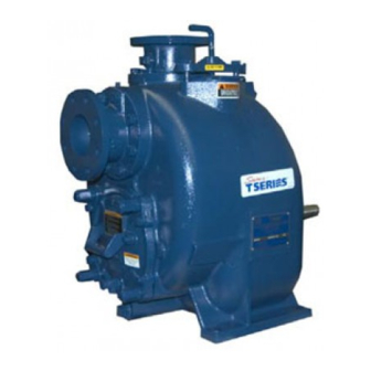
- Page 1 OM-05514-03 September 30, 2020 INSTALLATION, OPERATION, AND MAINTENANCE MANUAL WITH PARTS LIST SUPER T SERIES PUMP MODEL T6A60S-F4L GORMAN‐RUPP PUMPS www.grpumps.com 2020 Gorman‐Rupp Pumps Printed in U.S.A.
- Page 2 Register your new Gorman‐Rupp pump online at www.grpumps.com Valid serial number and e‐mail address required. The engine exhaust from this product contains chemicals known to the State of California to cause cancer, birth defects or other reproductive harm. RECORD YOUR PUMP MODEL AND SERIAL NUMBER Please record your pump model and serial number in the spaces provided below.
-
Page 3: Table Of Contents
TABLE OF CONTENTS INTRODUCTION ..........PAGE I - 1 SAFETY ‐... - Page 4 TABLE OF CONTENTS (continued) OPERATION ............. . PAGE C - 5 Lines With a Bypass .
-
Page 5: Introduction
Gorman‐ Rupp pump. This pump is a Super T Series, semi‐open impeller, self‐priming centrifugal model with a suction check valve. The pump also is designed with external Immediate hazards which WILL result in shimless adjusters for setting the wear plate to im... -
Page 6: Safety - Section A
SUPER T SERIES OM-05514 SAFETY ‐ SECTION A This information applies to Super T Se ing away from the unit to prevent injury ries engine driven pumps. Refer to the during automatic operation. Disconnect manual accompanying the engine be the positive battery cable before per... - Page 7 OM-05514 SUPER T SERIES When operating internal combustion engines in an enclosed area, make cer tain that exhaust fumes are piped to the outside. These fumes contain carbon Do not operate the pump against a monoxide, a deadly gas that is color...
-
Page 8: Installation - Section B
SUPER T SERIES OM-05514 INSTALLATION - SECTION B Review all SAFETY information in Section A. specific application. Since the pressure supplied to the pump is critical to performance and safety, Since pump installations are seldom identical, this be sure to limit the incoming pressure to 50% of the... -
Page 9: Preinstallation Inspection
OM-05514 SUPER T SERIES Before installing the battery, clean the positive and PREINSTALLATION INSPECTION negative cable connectors, and the battery termi nals. Secure the battery by tightening the The pump assembly was inspected and tested be holddown brackets. The terminals and clamps fore shipment from the factory. -
Page 10: Clearance
SUPER T SERIES OM-05514 the brake and blocking the wheels before attempt place by tightening the flange bolts and/or cou ing to operate the pump. plings. Lines near the pump must be independently sup To ensure sufficient lubrication and fuel supply to... -
Page 11: Sealing
OM-05514 SUPER T SERIES three or four times the cross section of the suction If it is necessary to position inflow close to the suc line, and the openings will not permit passage of tion inlet, install a baffle between the inflow and the solids larger than the solids handling capability of suction inlet at a distance 1‐1/2 times the diameter... -
Page 12: Float Switches
SUPER T SERIES OM-05514 Figure 2. Recommended Minimum Suction Line Submergence vs. Velocity FLOAT SWITCHES above the point where it bends along the bot tom. Direct the suction line toward the flow, and the float(s) away from the flow. If a stand... -
Page 13: Optional Submersible Transducer
OM-05514 SUPER T SERIES ENGINE (0.9) CONTROL (.76) (Emptying) (0.6) (Filling) (.46) OPERATING (0.3) RANGE CABLE (See Table Below) TETHER (.15) POINT (Emptying) (0.3) (0.6) (0.9) (1.2) APPROXIMATE FREE CORD LENGTH IN FT. (M) 1.25” Pipe (Filling) (Not Furnished) Figure 3. Float Switch Data OPTIONAL SUBMERSIBLE above the point where it bends along the bot... -
Page 14: Discharge Lines
SUPER T SERIES OM-05514 SUCTION LINE DISCHARGE LINE SIGNAL CABLE (ATTACH TO SUCTION LINE) SUCTION SUBMERSIBLE STRAINER TRANSDUCER (DOWNSTREAM FROM SUCTION) FLOW Figure 4. Typical Submersible Transducer Installation DISCHARGE LINES Siphoning If the application involves a high discharge head, gradually close the discharge Do not terminate the discharge line at a level lower throttling valve before stopping the pump. -
Page 15: Automatic Air Release Valve
OM-05514 SUPER T SERIES affect pump discharge capacity; however, the by lift station), if a manual shut‐off valve is in pass line should be at least 1 inch (25,4 mm) in di stalled anywhere in a bypass line, it must ameter to minimize the chance of plugging. -
Page 16: Air Release Valve Installation
SUPER T SERIES OM-05514 Consult the manual accompanying the Air Release pendently mounted in a horizontal position be Valve for additional information on valve installation tween the pump discharge port and the inlet side of and performance. the discharge check valve (see Figure 5). The inlet... -
Page 17: Operation - Section C
OM-05514 SUPER T SERIES OPERATION - SECTION C Review all SAFETY information in Section A. cated (see LUBRICATION in MAINTENANCE AND REPAIR). Follow the instructions on all tags, labels and This pump is self‐priming, but the pump should decals attached to the pump. -
Page 18: Starting
OM-05514 SUPER T SERIES Press and hold the white “AUTO” button on the STARTING control panel until the red “AUTO” light illuminates. The auto‐start system is now armed. NOTE The unit can continue to be started manually with This pump is equipped with an automat... -
Page 19: Optional Eps Control
OM-05514 SUPER T SERIES Stop the unit manually by pressing the “OFF/SET” f) SEt b.on... B ON setpoint, units of level. button. g) Hrn dLy... Horn on, A output delay time, 5-30 seconds, in OPTIONAL EPS CONTROL 5‐second increments. h) LO BAT... -
Page 20: Eps Functions
OM-05514 SUPER T SERIES EPS Functions ter false signals that could cause “nuisance” trip ping of the contacts. Actual functions of the control occur as follows: Power is applied to the unit. NOTE If the “Hrn dLy” is changed during the actual A out... -
Page 21: Span Adjustment
OM-05514 SUPER T SERIES Press 3 times and the LCD screen will display “Calibrate Zro”. Press until a character or number on the display changes. A manual shut‐off valve should not be Press to accept the entry and advance to “Cali... - Page 22 OM-05514 SUPER T SERIES Liquid Temperature And Overheating should also be checked if pump flow rate begins to drop. If a vacuum suction gauge has been in stalled, monitor and record the readings regularly The maximum liquid temperature for this pump is to detect strainer blockage.
- Page 23 OM-05514 SUPER T SERIES Pump Vacuum Check Safety Shutdown System The unit is equipped with a safety system to auto With the pump inoperative, install a vacuum gauge matically shut down the engine under certain con in the system, using pipe dope on the threads.
- Page 24 OM-05514 SUPER T SERIES ceeds design limits. If engine over‐temperature taining a large amount of solids, drain the pump, shutdown occurs, allow the unit to cool before re and flush it thoroughly with clean water. To prevent starting. large solids from clogging the drain port and pre...
- Page 25 SUPER T SERIES OM-05514 TROUBLESHOOTING - SECTION D Review all SAFETY information in Section A. 5. Close the suction and discharge valves. 6. Vent the pump slowly and cau tiously. 7. Drain the pump. Before attempting to open or service the pump: 1.
- Page 26 OM-05514 SUPER T SERIES TROUBLE POSSIBLE CAUSE PROBABLE REMEDY PUMP STOPS OR FAILS Impeller or other wearing parts Replace worn or damaged parts. TO DELIVER RATED worn or damaged. Check that impeller is properly cen tered and rotates freely. FLOW OR PRESSURE (cont.)
- Page 27 SUPER T SERIES OM-05514 equipped) between regularly scheduled inspec PREVENTIVE MAINTENANCE tions can indicate problems that can be corrected Since pump applications are seldom identical, and before system damage or catastrophic failure oc pump wear is directly affected by such things as curs.
- Page 28 SUPER T SERIES OM-05514 PUMP MAINTENANCE AND REPAIR ‐ SECTION E MAINTENANCE AND REPAIR OF THE WEARING PARTS OF THE PUMP WILL MAINTAIN PEAK OPERATING PERFORMANCE. STANDARD PERFORMANCE FOR PUMP MODEL T6A60S-F4L Based on 70_ F (21_ C) clear water at sea level Contact the Gorman‐Rupp Company to verify per...
- Page 29 OM-05514 SUPER T SERIES ILLUSTRATION PARTS PAGE Figure 1. Pump Model T6A60S-F4L PARTS LIST Pump Model T6A60S-F4L (From S/N 1731327 Up) If your pump serial number is followed by an “N”, your pump is NOT a standard production model. Contact the Gorman‐Rupp Company to verify part numbers.
- Page 30 SUPER T SERIES OM-05514 ILLUSTRATION DETAIL A Figure 2. Power Unit Kit MAINTENANCE & REPAIR PAGE E - 3...
- Page 31 OM-05514 SUPER T SERIES PARTS LIST Power Unit Kit ITEM PART PART NAME NUMBER BASE/FUEL TANK 41553-031 24150 ENGINE RAIL 34451-086 15080 ENGINE RAIL 34451-085 15080 EXHAUST ELBOW 31912-024 15990 WEATHER CAP S1246 LIFTING BAIL KIT 48274-801 MUFFLER GUARD ASSEMBLY...
- Page 32 SUPER T SERIES OM-05514 ILLUSTRATION Figure 3. Pump End Assembly MAINTENANCE & REPAIR PAGE E - 5...
- Page 33 OM-05514 SUPER T SERIES PARTS LIST Pump End Assembly ITEM PART NAME PART ITEM PART NAME PART NUMBER NUMBER PUMP CASING SEE NOTE BELOW BACK COVER NUT 31871-075 15000 PIPE PLUG P04 15079 O‐RING 25152-273 GASKET 25113-036 HEX NUT D06 17090 6"...
- Page 34 SUPER T SERIES OM-05514 ILLUSTRATION REPAIR ROTATING ASSEMBLY (REF) SEAL AREA DETAIL Figure 4. Repair Rotating Assembly MAINTENANCE & REPAIR PAGE E - 7...
- Page 35 OM-05514 SUPER T SERIES PARTS LIST Repair Rotating Assembly ITEM PART PART NAME NUMBER IMPELLER 38615-087 11010 1 7/8 CTG SEAL ASSY 46513-154 SEAL PLATE 38272-254 10010 OIL SEAL S1917 GASKET 10959G 20000 LOCK WASHER J08 15991 HEX HEAD CAP SCREW...
- Page 36 SUPER T SERIES OM-05514 ILLUSTRATION MODEL T6A60S LOCATE COUPLING AS DIMENSIONED Figure 5. Drive Assembly PARTS LIST ITEM PART PART NAME NUMBER COUPLING KIT 48112-001 -BUSHING 24131-345 -COUPLING ASSEMBLY 44165-011 -LOCKWASHER J06 15991 -LOCKWASHER 21171-536 -SOCKET HD CAPSCREW BD0606-1/2 15991...
- Page 37 OM-05514 SUPER T SERIES to ensure that it will remain inoperative. Close all PUMP AND SEAL DISASSEMBLY valves in the suction and discharge lines. AND REASSEMBLY For engine disassembly and repair, consult the lit Review all SAFETY information in Section A.
- Page 38 SUPER T SERIES OM-05514 casing. necessary and keep personnel away from suspended objects. Inspect the wear plate, and replace it if badly scored or worn. To remove the wear plate, disen gage the hardware (34 and 35). Inspect the back cover and wear plate O‐rings (18 Use Only Genuine Gorman-Rupp re...
- Page 39 OM-05514 SUPER T SERIES As the assemblies separate, the flexible portion of shaft (15) with the “V” notch positioned over the the coupling assembly (3) will remain on the shaft. shaft key. To remove the coupling from the shaft, unscrew the With the impeller rotation still blocked, see Figure 6 two allen head setscrews from the bushing (2).
- Page 40 SUPER T SERIES OM-05514 packed with it. A similar tool may be assembled us Use a pair of stiff wires with hooked ends to remove ing 1/2‐inch pipe (schedule 80 steel or malleable the stationary element and seat. iron) and a standard tee (see Figure 7). All threads An alternate method of removing the stationary are 1/2‐inch NPT.
- Page 41 OM-05514 SUPER T SERIES If bearing replacement is required, remove the out board bearing snap ring (20), and use a bearing puller to remove the bearings from the shaft. To prevent damage during removal from Shaft and Bearing Reassembly and Installation...
- Page 42 SUPER T SERIES OM-05514 hot plate may be used to heat the bearings. Bear against the bearing housing. Remove the lip seal ings should never be heated with a direct flame or sleeve. directly on a hot plate. NOTE If a hot oil bath is used to heat the bearings, both the oil and the container must be absolutely clean.
- Page 43 OM-05514 SUPER T SERIES sleeve O‐ring (30) and the external stationary seat cannot be realigned during reassembly. Reusing an old seal could result in prema O‐ring with a very small amount of “P-80 Emul ture failure. sion” or water. See Figure 8 for seal part identifica...
- Page 44 SUPER T SERIES OM-05514 and screw the impeller onto the shaft until it is proper clearance as described in Impeller Instal seated against the seal (see Figure 9). lation and Adjustment. Continue to screw the impeller onto the shaft. This If necessary to reuse an old seal in an emer...
- Page 45 OM-05514 SUPER T SERIES Slide the rotating portion of the seal (consisting of Rotating Assembly Installation the integral shaft sleeve, spring centering washer, (Figure 3) spring, bellows and retainer, and rotating element) NOTE onto the shaft until the seal faces contact.
- Page 46 SUPER T SERIES OM-05514 cure it with the hardware (34 and 35). The wear With the wear plate just touching the impeller, turn plate must be concentric to prevent binding when the two free adjusting screws until they engage the the back cover is installed.
- Page 47 OM-05514 SUPER T SERIES shown in Figure 5. Rotate the flexible portion of the Install the intermediate guards (16, Figure 4), and coupling until the tapped holes for the two set secure the drive flange to the engine bellhousing screws align with those in the bushing, and install with the hardware (6 and 7).
- Page 48 SUPER T SERIES OM-05514 Final Pump Assembly tioned horizontally to provide proper drainage. (Figure 1) Be sure the pump is secured to the base and en Bearings gine. Be sure to install any guards used over the ro (Figure 4) tating members.
- Page 49 For Warranty Information, Please Visit www.grpumps.com/warranty or call: U.S.: 419-755-1280 Canada: 519-631-2870 International: +1-419-755-1352 GORMAN‐RUPP PUMPS...
Need help?
Do you have a question about the SUPER T Series and is the answer not in the manual?
Questions and answers