Table of Contents
Advertisement
Quick Links
DS
OM-05144-01
October 10, 2000
Rev. J 07-30-08
INSTALLATION, OPERATION,
AND MAINTENANCE MANUAL
WITH PARTS LIST
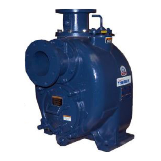
SUPER T SERIES PUMPS
MODELS
T6A3S-B
INCLUDING: /F, /FM /WW, /WWS
THE GORMAN-RUPP COMPANY D MANSFIELD, OHIO
www.grpumps.com
D
GORMAN-RUPP OF CANADA LIMITED
ST. THOMAS, ONTARIO, CANADA
Printed in U.S.A.
e
2000 The Gorman-Rupp Company
Advertisement
Table of Contents

Related Manuals for GORMAN-RUPP PUMPS T6A3S-B


Summary of Contents for GORMAN-RUPP PUMPS T6A3S-B
- Page 1 Rev. J 07-30-08 INSTALLATION, OPERATION, AND MAINTENANCE MANUAL WITH PARTS LIST SUPER T SERIES PUMPS MODELS T6A3S-B INCLUDING: /F, /FM /WW, /WWS THE GORMAN-RUPP COMPANY D MANSFIELD, OHIO www.grpumps.com GORMAN-RUPP OF CANADA LIMITED ST. THOMAS, ONTARIO, CANADA Printed in U.S.A.
- Page 2 Register your new Gorman-Rupp pump online at www.grpumps.com Valid serial number and e-mail address required. RECORD YOUR PUMP MODEL AND SERIAL NUMBER Please record your pump model and serial number in the spaces provided below. Your Gorman-Rupp distributor needs this information when you require parts or service. Pump Model: Serial Number:...
-
Page 3: Table Of Contents
TABLE OF CONTENTS INTRODUCTION ..........PAGE I −... - Page 4 TABLE OF CONTENTS (continued) TROUBLESHOOTING − SECTION D ......PAGE D − 1 PREVENTIVE MAINTENANCE .
-
Page 5: Introduction
SUPER T SERIES OM−05144 INTRODUCTION Thank You for purchasing a Gorman-Rupp pump. tenance procedures are used, and that any proce- Read this manual carefully to learn how to safely dures not addressed in this manual are performed only after establishing that neither personal safety install and operate your pump. -
Page 6: Safety − Section A
SUPER T SERIES OM−05144 SAFETY − SECTION A This information applies to Super T Se- which may damage the pump or endan- ries basic pumps. Gorman-Rupp has no ger personnel as a result of pump fail- control over or particular knowledge of ure. - Page 7 OM−05144 SUPER T SERIES Do not operate the pump against a Overheated pumps can cause severe closed discharge valve for long periods burns and injury. If overheating of the of time. If operated against a closed dis- pump occurs: charge valve, pump components will 1.
-
Page 8: Installation − Section Bpage B
OUTLINE DRAWING NOTE: OPTIONAL ASA OR DIN STANDARD SUCTION & DISCHARGE SPOOL FLANGES AVAILABLE Figure 1. Pump Model T6A3S-B, /F, /FM, /WW and /WWS INSTALLATION PAGE B − 1... -
Page 9: Preinstallation Inspection
OM−05144 SUPER T SERIES PREINSTALLATION INSPECTION POSITIONING PUMP Lifting The pump assembly was inspected and tested be- Pump unit weights will vary depending on the fore shipment from the factory. Before installation, mounting and drive provided. Check the shipping inspect the pump for damage which may have oc- tag on the unit packaging for the actual weight, and curred during shipment. -
Page 10: Line Configuration
SUPER T SERIES OM−05144 compatible with the liquid being pumped. If hose is Fittings used in suction lines, it must be the rigid-wall, rein- Suction lines should be the same size as the pump forced type to prevent collapse under suction. Us- inlet. -
Page 11: Suction Line Positioning
OM−05144 SUPER T SERIES If it is necessary to position inflow close to the suc- Suction Line Positioning tion inlet, install a baffle between the inflow and the The depth of submergence of the suction line is suction inlet at a distance 1 1/2 times the diameter critical to efficient pump operation. -
Page 12: Bypass Lines
SUPER T SERIES OM−05144 In high discharge head applications (more than 30 feet), an excessive amount of liquid may be by- passed and forced back to the wet well under the full working pressure of the pump; this will reduce If the application involves a high discharge overall pumping efficiency. -
Page 13: Automatic Air Release Valve
OM−05144 SUPER T SERIES moving the plug to prevent injury to per- liters] per minute) will occur when the valve is fully closed. Be sure the bypass sonnel from hot liquid. line is directed back to the wet well or tank to prevent hazardous spills. -
Page 14: Alignment
SUPER T SERIES OM−05144 Align spider insert type couplings by using calipers ALIGNMENT to measure the dimensions on the circumference of the outer ends of the coupling hub every 90_. The alignment of the pump and its power source is The coupling is in alignment when the hub ends critical for trouble-free mechanical operation. - Page 15 OM−05144 SUPER T SERIES tems using two or more belts, make certain that the belts are a matched set; unmatched sets will cause accelerated belt wear. Do not operate the pump without the guard in place over the rotating parts exposed rotating parts can catch cloth- ing, fingers, or tools, causing severe in- jury to personnel.
-
Page 16: Operation − Section C
OM−05144 SUPER T SERIES OPERATION − SECTION C Review all SAFETY information in Section A. Add liquid to the pump casing when: 1. The pump is being put into service for the Follow the instructions on all tags, labels and de- first time. -
Page 17: Operation
OM−05144 SUPER T SERIES If rotation is incorrect on a three-phase motor, have pump components will deteriorate, and a qualified electrician interchange any two of the the liquid could come to a boil, build three phase wires to change direction. If rotation is pressure, and cause the pump casing to incorrect on a single-phase motor, consult the liter- rupture or explode. -
Page 18: Strainer Check
OM−05144 SUPER T SERIES heated pump cautiously. It is recommended that shock waves can be transmitted to the pump and the pressure relief valve assembly be replaced at piping system. Close all connecting valves slowly. each overhaul, or any time the pump casing over- On engine driven pumps, reduce the throttle heats and activates the valve. - Page 19 OM−05144 SUPER T SERIES Temperatures up to 160_F (71_C) are considered to operate properly. Make certain that the bearing normal for bearings, and they can operate safely to lubricant is of the proper viscosity and at the cor- at least 180_F (82_C). rect level (see LUBRICATION in MAINTENANCE AND REPAIR).
- Page 20 SUPER T SERIES OM−05144 TROUBLESHOOTING − SECTION D Review all SAFETY information in Section A. Before attempting to open or service the pump: 1. Familiarize yourself with this manual. 2. Lock out or disconnect the power source to ensure that the pump will remain inoperative.
- Page 21 OM−05144 SUPER T SERIES TROUBLE POSSIBLE CAUSE PROBABLE REMEDY PUMP STOPS OR Strainer clogged. Check strainer and clean if neces- FAILS TO DELIVER sary. RATED FLOW OR PRESSURE Suction intake not submerged at Check installation and correct sub- proper level or sump too small. mergence as needed.
- Page 22 SUPER T SERIES OM−05144 equipped) between regularly scheduled inspec- PREVENTIVE MAINTENANCE tions can indicate problems that can be corrected Since pump applications are seldom identical, and before system damage or catastrophic failure oc- pump wear is directly affected by such things as curs.
- Page 23 MAINTENANCE AND REPAIR OF THE WEARING PARTS OF THE PUMP WILL MAINTAIN PEAK OPERATING PERFORMANCE. STANDARD PERFORMANCE FOR PUMP MODEL T6A3S-B, /F, /FM, /WW and /WWS Based on 70_F (21_C) clear water at sea level Contact the Gorman-Rupp Company to verify per- formance or part numbers.
- Page 24 OM−05144 SUPER T SERIES SECTION DRAWING PARTS PAGE Figure 1. Pump Model T6A3S−B ncluding /F, /FM, /WW and /WWS PAGE E − 2 MAINTENANCE & REPAIR...
- Page 25 OM−05144 SUPER T SERIES PARTS LIST Pump Model T6A3S−B (From S/N 1206492 Up) If your pump serial number is followed by an N", your pump is NOT a standard production model. Contact the Gorman-Rupp Company to verify part numbers. ITEM PART NAME PART MAT’L...
- Page 26 OM−05144 SUPER T SERIES SECTION DRAWING ASSEMBLED DRIVE END VIEW Figure 2. Repair Rotating Assemblies PAGE E − 4 MAINTENANCE & REPAIR...
- Page 27 OM−05144 SUPER T SERIES PARTS LIST Repair Rotating Assemblies Note: Order complete Repair Rotating Assemblies for /WW and /WWS models from the Pump Model Assembly Parts List on page E−3. Repair Rotating Assemblies for /WW models include all of the standard parts listed below.
- Page 28 OM−05144 SUPER T SERIES PUMP AND SEAL DISASSEMBLY AND REASSEMBLY Before attempting to open or service the pump: Review all SAFETY information in Section A. 1. Familiarize yourself with this man- ual. Follow the instructions on all tags, label and decals 2.
- Page 29 SUPER T SERIES OM−05144 Install the shaft key (23). Install a lathe dog on the NOTE drive end of the shaft (24) with the V" notch posi- An alternate method of removing the back cover tioned over the shaft key. from the pump casing is to remove the back cover nuts (13) and two diagonally opposing locking col- With the impeller rotation still blocked, see Figure 3...
- Page 30 OM−05144 SUPER T SERIES 9) and separate the seal plate (5) and gasket (6) from the bearing housing (10). Position the seal plate on a flat surface with the impeller side down. Use a wooden dowel or other suitable tool to press on the back side of the stationary seat until the APPROX.
- Page 31 SUPER T SERIES OM−05144 Shaft and Bearing Reassembly and Installation be cleaned and inspected in place. It is strongly recommended that the bearings (Figure 2) be replaced any time the shaft and bear- ings are removed. Clean the bearing housing, shaft and all compo- nent parts (except the bearings) with a soft cloth Clean the bearing housing, shaft and all compo- soaked in cleaning solvent.
- Page 32 OM−05144 SUPER T SERIES hot plate may be used to heat the bearings. Bear- Figure 2. Press the oil seal into the housing until the ings should never be heated with a direct flame or face is just flush with the machined surface on the directly on a hot plate.
- Page 33 SUPER T SERIES OM−05144 Inspect the seal components for wear, scoring, faces to ensure that they are free of any foreign grooves, and other damage that might cause leak- matter. age. If any components are worn, replace the com- To ease installation of the seal, lubricate the shaft plete seal;...
- Page 34 OM−05144 SUPER T SERIES Lubricate the external stationary seat O-ring with As the stationary seat becomes fully seated, the light oil. Slide the seal assembly onto the shaft until seal spring compresses, and the shaft sleeve will the external stationary seat O-ring engages the break the nylon shear ring.
- Page 35 SUPER T SERIES OM−05144 cuts on either end. If any components are worn, or A clearance of .025 to .040 inch (0,64 to 1,02 mm) the sleeve is damaged, replace the complete seal; between the impeller and the seal plate is recom- never mix old and new seal parts.
- Page 36 OM−05144 SUPER T SERIES Screw the four adjusting screws (11) into the NOTE tapped holes in the back cover plate until they are If the suction or discharge flanges were removed, just flush with the machined surface on the back replace the respective gaskets, apply ‘Permatex side of the cover plate.
- Page 37 SUPER T SERIES OM−05144 rotating assembly to the pump casing. Perform the LUBRICATION back cover adjustment procedure described Seal Assembly above to obtain the proper face clearance. (Figure 2) Before starting the pump, remove the vented plug PRESSURE RELIEF VALVE (11) and fill the seal cavity with approximately 64 MAINTENANCE ounces (1,9 liters) SAE No.
- Page 38 For U.S. and International Warranty Information, Please Visit www.grpumps.com/warranty or call: U.S.: 419−755−1280 International: +1−419−755−1352 For Canadian Warranty Information, Please Visit www.grcanada.com/warranty or call: 519−631−2870 THE GORMAN-RUPP COMPANY D MANSFIELD, OHIO GORMAN-RUPP OF CANADA LIMITED ST. THOMAS, ONTARIO, CANADA...
Need help?
Do you have a question about the T6A3S-B and is the answer not in the manual?
Questions and answers