Table of Contents
Advertisement
Quick Links
CDSW
OM-02908-OB01
June 20, 1986
Rev. I 04/18/02
INSTALLATION, OPERATION,
AND MAINTENANCE MANUAL
WITH PARTS LIST
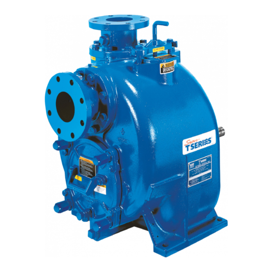
T SERIES PUMP
MODEL
T6A65---B
INCLUDING: /F, /FM
THE GORMAN-RUPP COMPANY D MANSFIELD, OHIO
GORMAN-RUPP OF CANADA LIMITED
ST. THOMAS, ONTARIO, CANADA
D
Printed in U.S.A.
E
Copyright by the Gorman-Rupp Company
Advertisement
Table of Contents

Related Manuals for GORMAN-RUPP PUMPS T6A65-B


Summary of Contents for GORMAN-RUPP PUMPS T6A65-B
- Page 1 CDSW OM-02908-OB01 June 20, 1986 Rev. I 04/18/02 INSTALLATION, OPERATION, AND MAINTENANCE MANUAL WITH PARTS LIST T SERIES PUMP MODEL T6A65---B INCLUDING: /F, /FM THE GORMAN-RUPP COMPANY D MANSFIELD, OHIO GORMAN-RUPP OF CANADA LIMITED ST. THOMAS, ONTARIO, CANADA Printed in U.S.A. Copyright by the Gorman-Rupp Company...
- Page 2 TABLE OF CONTENTS INTRODUCTION ..........PAGE I --- 1 SAFETY --- SECTION A .
-
Page 3: Table Of Contents
TABLE OF CONTENTS (continued) TROUBLESHOOTING --- SECTION D ......PAGE D --- 1 PREVENTIVE MAINTENANCE . - Page 4 T SERIES OM -- 02908 INTRODUCTION This Installation, Operation, and Maintenance valve. The pump is designed for handling chemical manual is designed to help you achieve the best and low Ph resistance residues and slurries con- performance and longest life from your Gorman- taining large entrained solids.
- Page 5 T SERIES OM -- 02908 SAFETY --- SECTION A This information applies to the T Series slurries containing large entrained sol- basic pumps. Gorman-Rupp has no ids. Do not attempt to pump volatile, cor- control over or particular knowledge of rosive, or flammable materials which the power source which will be used.
- Page 6 OM -- 02908 T SERIES of time. If operated against a closed dis- charge valve, pump components will deteriorate, and the liquid could come to a boil, build pressure, and cause the Use lifting and moving equipment in pump casing to rupture or explode. good repair and with adequate capacity to prevent injuries to personnel or dam- age to equipment.
- Page 7 See Figure 1 for the approximate physical dimen- configuration, and priming must be tailored to the sions of this pump. OUTLINE DRAWING NOTE: OPTIONAL ASA OR DIN STANDARD SUCTION & DISCHARGE SPOOL FLANGES AVAILABLE Figure 1. Pump Model T6A65-B INSTALLATION PAGE B -- 1...
- Page 8 OM -- 02908 T SERIES PREINSTALLATION INSPECTION POSITIONING PUMP Lifting The pump assembly was inspected and tested be- fore shipment from the factory. Before installation, Use lifting equipment with a capacity of at least inspect the pump for damage which may have oc- 4050 pounds (1837,1 kg).
- Page 9 T SERIES OM -- 02908 Fittings compatible with the liquid being pumped. If hose is used in suction lines, it must be the rigid-wall, rein- Suction lines should be the same size as the pump forced type to prevent collapse under suction. Us- inlet.
- Page 10 OM -- 02908 T SERIES Suction Line Positioning If it is necessary to position inflow close to the suc- tion inlet, install a baffle between the inflow and the The depth of submergence of the suction line is suction inlet at a distance 1 1/2 times the diameter critical to efficient pump operation.
- Page 11 T SERIES OM -- 02908 from excessive shock pressure and reverse rota- It is also recommended that pipe unions be in- tion when it is stopped. stalled at each 90_ elbow in a bypass line to ease disassembly and maintenance. In high discharge head applications (more than 30 feet), an excessive amount of liquid may be by- passed and forced back to the wet well under the...
- Page 12 OM -- 02908 T SERIES drain the liquid from the pump by re- presses the spring and closes the valve (Figure 4). The valve will remain closed, reducing the bypass moving the casing drain plug. Use cau- of liquid to 1 to 5 gallons (3.8 to 19 liters) per min- tion when removing the plug to prevent ute, until the pump loses its prime or stops.
- Page 13 T SERIES OM -- 02908 DISCHARGE PIPE CLEAN-OUT COVER INSTALL AIR RELEASE VALVE IN HORIZONTAL POSITION DISCHARGE CHECK VALVE 90_ LONG RADIUS ELBOW SUPPORT PUMP DISCHARGE BRACKET SELF-PRIMING CENTRIFUGAL PUMP BLEED LINE 1” (25,4 MM) DIA. MIN. (CUSTOMER FURNISHED) EXTEND 6” SUCTION LINE (152,4 MM)
- Page 14 OM -- 02908 T SERIES When checking alignment, disconnect the power source to ensure that the pump will remain inoperative. Adjusting the alignment in one direction may alter the alignment in another direc- Figure 6B. Aligning Non-Spider tion. check each procedure after altering Type Couplings alignment.
- Page 15 T SERIES OM -- 02908 Do not operate the pump without the guard in place over the rotating parts exposed rotating parts can catch cloth- ing, fingers, or tools, causing severe in- jury to personnel. MISALIGNED: MISALIGNED: ALIGNED: SHAFTS SHAFTS SHAFTS PARALLEL AND NOT PARALLEL...
- Page 16 OM -- 02908 T-SERIES OPERATION --- SECTION C Review all SAFETY information in Section A. Add liquid to the pump casing when: 1. The pump is being put into service for the Follow the instructions on all tags, labels and de- first time.
- Page 17 OM -- 02908 T-SERIES closed discharge throttling valve for observing the direction of the motor shaft, or cool- ing fan. long periods of time. If operated against a closed discharge throttling valve, If rotation is incorrect on a three-phase motor, have pump components will deteriorate, and a qualified electrician interchange any two of the the liquid could come to a boil, build...
- Page 18 OM -- 02908 T-SERIES STOPPING does occur, stop the pump immediately and allow it to cool before servicing it. Approach any over- heated pump cautiously. It is recommended that Never halt the flow of liquid suddenly. If the liquid the pressure relief valve assembly be replaced at being pumped is stopped abruptly, damaging each overhaul, or any time the pump casing over- shock waves can be transmitted to the pump and...
- Page 19 OM -- 02908 T-SERIES AND REPAIR). Bearing overheating can also be against the housing. Record this temperature for future reference. caused by shaft misalignment and/or excessive vi- bration. A sudden increase in bearing temperature is a warning that the bearings are at the point of failing When pumps are first started, the bearings may to operate properly.
-
Page 20: Troubleshooting
T SERIES OM -- 02908 TROUBLESHOOTING --- SECTION D Review all SAFETY information in Section A. Before attempting to open or service the pump: 1. Familiarize yourself with this manual. 2. Lock out or disconnect the power source to ensure that the pump will remain inoperative. - Page 21 OM -- 02908 T SERIES TROUBLE POSSIBLE CAUSE PROBABLE REMEDY Air leak in suction line. Correct leak. PUMP STOPS OR FAILS TO DELIVER Lining of suction hose collapsed. Replace suction hose. RATED FLOW OR PRESSURE Leaking or worn seal or pump gasket. Check pump vacuum.
-
Page 22: Preventive Maintenance
T SERIES OM -- 02908 TROUBLE POSSIBLE CAUSE PROBABLE REMEDY EXCESSIVE NOISE Cavitation in pump. Reduce suction lift and/or friction losses in suction line. Record vac- uum and pressure gauge readings and consult local representative or factory. Pumping entrained air. Locate and eliminate source of air bubble. - Page 23 OM -- 02908 T SERIES Preventive Maintenance Schedule Service Interval* Item Daily Weekly Monthly Semi- Annually Annually General Condition (Temperature, Unusual Noises or Vibrations, Cracks, Leaks, Loose Hardware, Etc.) Pump Performance (Gauges, Speed, Flow) Bearing Lubrication Seal Lubrication (And Packing Adjustment, If So Equipped) V-Belts (If So Equipped) Air Release Valve Plunger Rod (If So Equipped)
-
Page 24: Pump Maintenance And Repair
MAINTENANCE AND REPAIR OF THE WEARING PARTS OF THE PUMP WILL MAINTAIN PEAK OPER- ATING PERFORMANCE. STANDARD PERFORMANCE FOR PUMP MODEL T6A65-B, T6A65-- B /F And T6A65-- B /FM Based on 70_F (21_C) clear water at sea level Contact the Gorman-Rupp Company to verify per- formance or part numbers. - Page 25 OM -- 02908 T-SERIES SECTION DRAWING Figure 1. Pump Model T6A65---B, T6A65---B /F And T6A65---B /FM PAGE E -- 2 MAINTENANCE & REPAIR...
-
Page 26: Parts Lists
OM -- 02908 T-SERIES PARTS LIST Pump Model T6A65---B, T6A65---B /F And T6A65---B /FM (From S/N 859000 up) If your pump serial number is followed by an “N”, your pump is NOT a standard production model. Contact the Gorman-Rupp Company to verify part numbers. ITEM PART NAME PART... - Page 27 OM -- 02908 T-SERIES SECTION DRAWING DRIVE END VIEW Figure 2. 44163---108 Repair Rotating Assembly PAGE E -- 4 MAINTENANCE & REPAIR...
- Page 28 OM -- 02908 T-SERIES PARTS LIST 44163---108 Repair Rotating Assembly ITEM PART NAME PART MAT’L ITEM PART NAME PART MAT’L NUMBER CODE NUMBER CODE STUD C0807 17090 IMPELLER 10958 1718H LOCKWASHER 17090 SEAL ASSEMBLY 46512--- 074 --- --- --- HEX NUT 17090 INBOARD BALL BEARING 23276--- 009 --- --- ---...
-
Page 29: Pump And Seal Disassembly And Reassembly
OM -- 02908 T SERIES PUMP AND SEAL DISASSEMBLY 2. Disconnect or lock out the power source to ensure that the pump will AND REASSEMBLY remain inoperative. 3. Allow the pump to completely cool Review all SAFETY information in Section A. if overheated. -
Page 30: Rotating Assembly Removal
T SERIES OM -- 02908 Individual parts are not sold separately. Turn Counterclockwise Rotating Assembly Removal Lathe Dog Arm (Figure 2) “V” Notch Heavy Shaft Key The rotating assembly may be serviced without Bar Stock disconnecting the suction or discharge piping; Impeller Shaft however, the power source must be removed to Lathe Dog... -
Page 31: Impeller Removal
OM -- 02908 T SERIES Use caution when lifting the rotating assembly to avoid injury to personnel or damage to the assem- bly. Shaft and bearing disassembly in the field Remove the bearing housing O-ring (10). is not recommended. These operations should be performed only in a properly- equipped shop by qualified personnel. -
Page 32: Shaft And Bearing Reassembly And Installation
T SERIES OM -- 02908 Position the inboard oil seal (23) in the bearing housing bore with the lip positioned as shown in Figure 2. Press the oil seal into the housing until the face is just flush with the machined surface on the Bearings must be kept free of all dirt and housing. -
Page 33: Seal Installation
OM -- 02908 T SERIES Clean the seal cavity and shaft with a cloth soaked in fresh cleaning solvent. Inspect the stationary seat bore in the seal plate for dirt, nicks and burrs, and remove any that exist. The stationary seat bore When installing the bearings onto the must be completely clean before installing the shaft, never press or hit against the outer... -
Page 34: Impeller Installation
T SERIES OM -- 02908 SPRING RETAINER SPACER SEAL PLATE WASHER O-RINGS IMPELLER BELLOWS IMPELLER SHAFT IMPELLER SHIMS STATIONARY SEAT SPRING CENTERING STATIONARY WASHER ROTATING ELEMENT DRIVE BAND ELEMENT Figure 5. 46512-- 074 Seal Assembly Install the seal spring, seal washer (9), and spring centering washer. -
Page 35: Rotating Assembly Installation
OM -- 02908 T SERIES Install the same thickness of impeller adjusting bly into the pump casing using the installation tool. shims (8) as previously removed. Apply ‘Never- Be careful not to damage the O-ring. Seez’ or equivalent to the shaft threads and screw Install the four sets of rotating assembly adjusting the impeller onto the shaft until tight. -
Page 36: Back Cover Installation
T SERIES OM -- 02908 Back Cover Installation threads. Position the valve as shown in Figure 1 with the discharge port pointing down. (Figure 1) Final Pump Assembly If the wear plate (23) was removed for replace- ment, carefully center it on the back cover and se- (Figure 1) cure it with the hardware (26 and 27). -
Page 37: Power Source
OM -- 02908 T SERIES quired, add SAE No. 30 non-detergent oil through the hole for the air vent (6). Do not over-lubricate. Over-lubrication can cause the bearings to over- heat, resulting in premature bearing failure. Monitor the condition of the bearing lubri- cant regularly for evidence of rust or mois- ture condensation. - Page 38 For U.S. and International Warranty Information, Please Visit www.grpumps.com/warranty or call: U.S.: 419−755−1280 International: +1−419−755−1352 For Canadian Warranty Information, Please Visit www.grcanada.com/warranty or call: 519−631−2870 THE GORMAN-RUPP COMPANY D MANSFIELD, OHIO GORMAN-RUPP OF CANADA LIMITED ST. THOMAS, ONTARIO, CANADA...
Need help?
Do you have a question about the T6A65-B and is the answer not in the manual?
Questions and answers