Table of Contents

Related Manuals for GORMAN-RUPP PUMPS T6A61S-B


Summary of Contents for GORMAN-RUPP PUMPS T6A61S-B
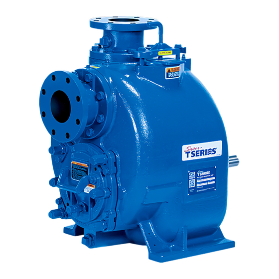
- Page 1 OM-05268-01 March 11, 2002 Rev. K 04‐18‐18 INSTALLATION, OPERATION, AND MAINTENANCE MANUAL WITH PARTS LIST SUPER T SERIES PUMPS MODELS T6A61S-B INCLUDING: /F, /FM GORMAN‐RUPP PUMPS www.grpumps.com 2002 Gorman‐Rupp Pumps Printed in U.S.A.
- Page 2 Register your new Gorman‐Rupp pump online at www.grpumps.com Valid serial number and e‐mail address required. RECORD YOUR PUMP MODEL AND SERIAL NUMBER Please record your pump model and serial number in the spaces provided below. Your Gorman‐Rupp distributor needs this information when you require parts or service. Pump Model: Serial Number:...
-
Page 3: Table Of Contents
TABLE OF CONTENTS INTRODUCTION ..........PAGE I - 1 SAFETY - SECTION A . - Page 4 TABLE OF CONTENTS (continued) BEARING TEMPERATURE CHECK ......... . PAGE C - 4 TROUBLESHOOTING - SECTION D .
-
Page 5: Introduction
SUPER T SERIES OM-05268 INTRODUCTION Thank You for purchasing a Gorman‐Rupp pump. HAZARD AND INSTRUCTION Read this manual carefully to learn how to safely DEFINITIONS install and operate your pump. Failure to do so could result in personal injury or damage to the The following are used to alert maintenance per... -
Page 6: Safety - Section A
SUPER T SERIES OM-05268 SAFETY - SECTION A This information applies to Super T Se riesr basic pumps. Gorman‐Rupp has no control over or particular knowledge of the power source which will be used. This pump is designed to handle liquids Refer to the manual accompanying the containing large entrained solids or power source before attempting to be... - Page 7 OM-05268 SUPER T SERIES Do not operate the pump against a Do not operate the pump without the closed discharge valve for long periods of time. If operated against a closed dis guards in place over the rotating parts. charge valve, pump components will Exposed rotating parts can catch cloth...
-
Page 8: Installation - Section B
SUPER T SERIES OM-05268 INSTALLATION - SECTION B Review all SAFETY information in Section A. specific application. Since the pressure supplied to the pump is critical to performance and safety, Since pump installations are seldom identical, this be sure to limit the incoming pressure to 50% of section offers only general recommendations and the maximum permissible operating pressure as practices required to inspect, position, and ar... -
Page 9: Preinstallation Inspection
OM-05268 SUPER T SERIES PREINSTALLATION INSPECTION POSITIONING PUMP The pump assembly was inspected and tested be fore shipment from the factory. Before installation, inspect the pump for damage which may have oc Death or serious personal injury and curred during shipment. Check as follows: damage to the pump or components can occur if proper lifting procedures a. -
Page 10: Suction And Discharge Piping
SUPER T SERIES OM-05268 (229 mm) must be maintained to permit removal of these gauges are desired for pumps that are not the cover. tapped, drill and tap the suction and discharge lines not less than 18 inches (457,2 mm) from the suction and discharge ports and install the lines. -
Page 11: Suction Lines In Sumps
OM-05268 SUPER T SERIES tight seal. Follow the sealant manufacturer's rec If two suction lines are installed in a single sump, ommendations when selecting and applying the the flow paths may interact, reducing the efficiency pipe dope. The pipe dope should be compatible of one or both pumps. -
Page 12: Discharge Lines
SUPER T SERIES OM-05268 minimize the chance of plugging. DISCHARGE LINES Siphoning In low discharge head applications (less than 30 feet or 9 meters), it is recommended that the by Do not terminate the discharge line at a level lower pass line be run back to the wet well, and located 6 than that of the liquid being pumped unless a si... -
Page 13: Automatic Air Release Valve
OM-05268 SUPER T SERIES AUTOMATIC AIR RELEASE VALVE When properly installed, a Gorman‐Rupp Auto matic Air Release Valve will permit air to escape If a manual shut‐off valve is installed in through the bypass line and then close automati a bypass line, it must not be left closed cally when the pump is fully primed and pumping during operation. -
Page 14: Alignment
SUPER T SERIES OM-05268 DISCHARGE PIPE CLEAN‐OUT COVER INSTALL AIR RELEASE VALVE IN HORIZONTAL POSITION DISCHARGE CHECK VALVE 90_ LONG RADIUS ELBOW SUPPORT PUMP DISCHARGE BRACKET SELF‐PRIMING CENTRIFUGAL PUMP BLEED LINE 1” (25,4 MM) DIA. MIN. (CUSTOMER FUR NISHED) DO NOT EX SUCTION TEND BELOW PUMP LINE... -
Page 15: Coupled Drives
OM-05268 SUPER T SERIES Adjusting the alignment in one direction may alter the alignment in another direc tion. check each procedure after altering alignment. Coupled Drives Figure 5. Aligning Non‐Spider Type Couplings Check parallel adjustment by laying a straightedge across both coupling rims at the top, bottom, and When using couplings, the axis of the power side. -
Page 16: Drive Belt Tensioning
SUPER T SERIES OM-05268 Select pulleys that will match the proper speed ra DRIVE BELT TENSIONING tio; overspeeding the pump may damage both General Rules of Tensioning pump and power source. For new drive belts, check the tension after 5, 20 and 50 hours of operation and re‐tension as re... -
Page 17: Operation - Section C
OM-05268 SUPER T SERIES OPERATION - SECTION C Review all SAFETY information in Section A. 2. The pump has not been used for a consider able length of time. Follow the instructions on all tags, labels and de 3. The liquid in the pump casing has evapo cals attached to the pump. -
Page 18: Operation
OM-05268 SUPER T SERIES Consult the operating manual furnished with the filled, adjust the throttling valve to the required flow power source before attempting to start the power rate. source. If an electric motor is used to drive the pump, re move V‐belts, couplings, or otherwise disconnect the pump from the motor before checking motor Do not operate the pump against a... -
Page 19: Strainer Check
OM-05268 SUPER T SERIES Open the suction line, and read the vacuum gauge gaged to be ejected with great force. Af with the pump primed and at operation speed. ter the pump completely cools, drain the Shut off the pump. The vacuum gauge reading will liquid from the pump by removing the immediately drop proportionate to static suction casing drain plug. - Page 20 OM-05268 SUPER T SERIES few hours, or if it has been pumping liquids con Checking bearing temperatures by hand is inaccu taining a large amount of solids, drain the pump, rate. Bearing temperatures can be measured ac and flush it thoroughly with clean water. To prevent curately by placing a contact‐type thermometer large solids from clogging the drain port and pre...
- Page 21 SUPER T SERIES OM-05268 TROUBLESHOOTING - SECTION D Review all SAFETY information in Section A. Before attempting to open or service the pump: 1. Familiarize yourself with this manual. 2. Lock out or disconnect the power source to ensure that the pump will remain inoperative.
- Page 22 OM-05268 SUPER T SERIES TROUBLE POSSIBLE CAUSE PROBABLE REMEDY Suction intake not submerged at Check installation and correct PUMP STOPS OR FAILS TO DELIVER proper level or sump too small. submergence as needed. RATED FLOW OR Impeller or other wearing parts worn Replace worn or damaged parts.
- Page 23 SUPER T SERIES OM-05268 equipped) between regularly scheduled inspec PREVENTIVE MAINTENANCE tions can indicate problems that can be corrected Since pump applications are seldom identical, and before system damage or catastrophic failure oc pump wear is directly affected by such things as curs.
- Page 24 OM-05268 SUPER T SERIES PUMP MAINTENANCE AND REPAIR - SECTION E MAINTENANCE AND REPAIR OF THE WEARING PARTS OF THE PUMP WILL MAINTAIN PEAK OPERATING PERFORMANCE. STANDARD PERFORMANCE FOR PUMP MODEL T6A61S‐B, /F, /FM Based on 70 F (21 C) clear water at sea level Contact the Gorman‐Rupp Company to verify per...
- Page 25 OM-05268 SUPER T SERIES ILLUSTRATION PARTS PAGE Figure 1. Pump Model T6A61S-B ncluding /F, /FM PAGE E - 2 MAINTENANCE & REPAIR...
- Page 26 OM-05268 SUPER T SERIES PARTS LIST Pump Model T6A61S-B ncluding /F, /FM (From S/N 1240490 Up) If your pump serial number is followed by an “N”, your pump is NOT a standard production model. Contact the Gorman‐Rupp Company to verify part numbers.
- Page 27 OM-05268 SUPER T SERIES ILLUSTRATION SEAL AREA DETAIL Figure 2. Repair Rotating Assembly PAGE E - 4 MAINTENANCE & REPAIR...
- Page 28 OM-05268 SUPER T SERIES PARTS LIST Repair Rotating Assembly ITEM PART PART NAME NUMBER IMPELLER 38615-087 17070 SEAL ASSEMBLY 46512-192 ADJ SHIM SET 5091 17090 SEAL PLATE 38272-254 17070 GASKET 10959G 20000 OIL SEAL S1917 HEX HEAD CAP SCREW B0805-1/2 17000 LOCK WASHER J08 17090 BEARING HOUSING...
- Page 29 OM-05268 SUPER T SERIES PUMP AND SEAL DISASSEMBLY pump integrity are compromised by such practices. AND REASSEMBLY Review all SAFETY information in Section A. Follow the instructions on all tags, label and decals Before attempting to open or service the attached to the pump.
- Page 30 SUPER T SERIES OM-05268 Suction Check Valve Removal adequate protective clothing when working on the pump or piping. (Figure 1) If the check valve assembly (23) is to be serviced, remove the check valve pin (22), reach through the back cover opening and pull the complete assem bly from the suction flange (21).
- Page 31 OM-05268 SUPER T SERIES bly has been removed from the pump casing. APPROX. 6 IN. (152 MM) LONG Turn Counterclockwise APPROX. 14 IN. (356 MM) LONG Lathe Dog Arm Figure 4. Rotating Assembly Tool To install the tool, remove the vented plug (10, Fig “V”...
- Page 32 SUPER T SERIES OM-05268 and gasket (5) from the bearing housing (9). Posi be replaced any time the shaft and bear tion the seal plate on a flat surface with the impeller ings are removed. side down. Use a wooden dowel or other suitable Clean the bearing housing, shaft and all compo...
- Page 33 OM-05268 SUPER T SERIES Heat the bearings to a uniform temperature no higher than 250 F (120 C) and slide the bearings onto the shaft, one at a time, until they are fully seated. This should be done quickly, in one con Most cleaning solvents are toxic and tinuous motion, to prevent the bearings from cool...
- Page 34 SUPER T SERIES OM-05268 Lubricate the bearing housing as indicated in LU any time the old seal is removed from the BRICATION. pump. Wear patterns on the finished faces cannot be realigned during reassembly. Reusing an old seal could result in prema Seal Installation ture failure.
- Page 35 OM-05268 SUPER T SERIES RETAINER SEAL PLATE SPRING O‐RINGS IMPELLER BELLOWS IMPELLER SHAFT ROTATING STATIONARY ELEMENT ELEMENT IMPELLER SHIMS STATIONARY DRIVE BAND SEAT Figure 5. Seal Assembly the rotating element, bellows and retainer) onto the shaft. Apply firm, steady pressure on the seal re tainer until it slides onto the shaft and the seal faces contact.
- Page 36 SUPER T SERIES OM-05268 Install the rotating assembly adjusting shims (33) to the shaft, making future removal difficult and secure the rotating assembly to the pump cas or impossible without damage to the im ing with the hardware (14 and 32). peller or shaft.
- Page 37 OM-05268 SUPER T SERIES in the locking collars realign with the tapped screw USE TWO USE TWO REMAINING OPPOSING ADJUSTING SCREWS AND holes in the back cover plate. Secure the locking BACK COVER NUTS LOCKING COLLARS TO collars to the back cover plate with the hardware SET FACE CLEARANCE TO PRESS BACK COVER...
- Page 38 SUPER T SERIES OM-05268 Final Pump Assembly Bearings (Figure 1) (Figure 2) Install the shaft key (22, Figure 2) and reconnect The bearing housing was fully lubricated when the power source. Be sure to install any guards shipped from the factory. Check the oil level regu used over the rotating members.
- Page 39 For Warranty Information, Please Visit www.grpumps.com/warranty or call: U.S.: 419-755-1280 Canada: 519-631-2870 International: +1-419-755-1352 GORMAN‐RUPP PUMPS...
Need help?
Do you have a question about the T6A61S-B and is the answer not in the manual?
Questions and answers