Table of Contents
Advertisement
Quick Links
Advertisement
Table of Contents

Related Manuals for Lasertec HV2G


Summary of Contents for Lasertec HV2G
- Page 1 H V 2 G R O T A R Y L A S E R I N S T R U C T I O N M A N U A L...
- Page 2 SAFETY Read the following safety instructions before ▪ Tool service must be performed only by attempting to operate this product. qualified repair personnel. Repairs, service Keep these instructions in a safe place or store or maintenance performed by unqualified in the carry case for future reference. personnel will void the warranty.
- Page 3 WARNING: DO NOT DISASSEMBLE ▪ Do not set up the tool at a position where THE LASER. There are no user serviceable the laser beam can cross any person at head height. parts inside. Disassembling the laser will ▪ Do not let children come in contact with the void all warranties on the product.
-
Page 4: Item Checklist
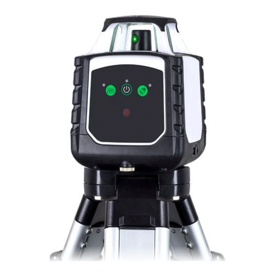
Please ensure the following items are included with your laser level. If anything is missing please contact your retailer. INCHES Remote control Laser glasses Detector & clamp Mount Laser target Lasertec HV2R 4x AA rechargeable batteries (laser level) 1x 9V alkaline battery (detector) 2x AAA alkaline Tripod 3m staff... - Page 5 LASER OVERVIEW: FRONT Rotating laser port Control panel Charging port Battery screw...
- Page 6 LASER OVERVIEW: BASE Battery screw Battery door 5/8” x 11 thread for horizontal operation on a tripod Vertical mounting point...
- Page 7 LASER OVERVIEW: CONTROL PANEL Power indicator Manual / automatic mode indicator Tilt alarm indicator Manual / automatic mode Tilt alarm Power...
-
Page 8: Remote Control Overview
REMOTE CONTROL OVERVIEW Button indicator Manual / automatic mode Grade adjustment Grade adjustment Grade adjustment Grade adjustment... - Page 9 REMOTE CONTROL OVERVIEW: BACK Battery compartment...
- Page 10 DETECTOR OVERVIEW: FRONT LCD display screen Sound on / off Laser sensor Coarse / fine detection Power Speaker...
- Page 11 DETECTOR OVERVIEW: BACK LCD display screen Staff clamp thread Battery compartment...
-
Page 12: Using Your Laser
USING YOUR LASER POWER SUPPLY Indoor charger ▪ The instrument is supplied with four AA Ni-Mh batteries as its standard power ▪ The indoor charger is for indoor use only. source. ▪ Do not store in locations where moisture ▪ The instrument can also be powered by can be present or where the charger could four AA alkaline batteries. - Page 13 POWER SUPPLY (continued) Charging the rechargeable batteries Removing & inserting the rechargeable batteries ▪ Insert the charger into the charging port on the instrument. Progress will be shown by ▪ Unscrew and remove the battery cover the power indicator display on the charger door and the batteries.
- Page 14 HORIZONTAL MEASUREMENT SET UP Level surface set up Tripod set up ▪ Select a place as close and practical ▪ Select a place as close and practical to the work site as possible, and ensure to the work site as possible, and ensure that the location is clear of traffic.
- Page 15 VERTICAL MEASUREMENT SET UP Level surface set up Tripod set up ▪ Select a place as close and practical to ▪ Select a place as close and practical to the work site as possible, and ensure that the work site as possible, and ensure that the location is clear of traffic.
-
Page 16: Operation
OPERATION Tilt alarm Powering on ▪ Once the instrument has been levelled off ▪ Press the power button once and the the tilt alarm can be enabled by pressing instrument will power begin the tilt alarm button on the instrument. automatically self-levelling. -
Page 17: Using Your Remote
OPERATION (continued) USING YOUR REMOTE Power supply Setting up a grade / slope ▪ The remote is powered by two AAA ▪ To create a slope / grade, enter into manual mode by pressing the manual alkaline battery. / automatic mode button on either the Battery replacement instrument or remote control. -
Page 18: Using Your Detector
USING YOUR DETECTOR Power supply Detector operation ▪ The detector is powered by a 9V alkaline ▪ Switch the detector on by pressing the battery. power button. The speaker will beep once indicating the instrument is operating. Mounting the staff clamp ▪... - Page 19 USING YOUR DETECTOR (continued) Detector position for horizontal beams Detector position for vertical beams...
- Page 20 MOUNT OVERVIEW Screw fixing point Screw fixing point Hook 5/8” x 11 thread for 5/8” x 11 thread for vertical operation vertical operation on a tripod on a tripod Locking lever...
- Page 21 USING THE MOUNT Mounting via screw fixing points ▪ Attach the mount via the hook onto the back of the instrument. ▪ Push the locking lever to secure in place. ▪ Fix a screw into a secure surface and hook the mount over the screw. Ensure that the mount has a strong hold before releasing your hands.
-
Page 22: Checking Calibration
CHECKING CALIBRATION Before doing any precision levelling it is ▪ The difference should be within 6mm at 30m. advised to check the calibration of the ▪ If the instrument is out of calibration it is instrument. advised to send it in to Spot-on. (see www.spoton.com.au for details) ▪... -
Page 23: Troubleshooting
TROUBLE SHOOTING Error Cause & Solution ▪ Check the batteries. They may be in the wrong way or need replacing. Laser does not ▪ Check the battery compartment for signs of damage. Ensure they are clean and not bent. turn on ▪... -
Page 24: Care And Maintenance
CARE AND MAINTENANCE ▪ Reflective surfaces such as glass may reflect ▪ The operator should check the accuracy the beam, causing two beams to strike the of the instrument before precision levelling detector at the same time. This may create is attempted. -
Page 25: Warranty
WARRANTY The Lasertec HV2G comes with a 3 (three) year manufacturers warranty. AUSTRALIA NEW ZEALAND “Our goods come with guarantees that For more information please visit cannot be excluded under the Australian consumerprotection.govt.nz Consumer Law. You are entitled to a... -
Page 26: Customer Support
CUSTOMER SUPPORT To assist you with any queries or technical questions please contact customer support Australia: 1300 658 338 New Zealand: 0800 367 527... -
Page 27: Specifications
SPECIFICATIONS Specifications Lasertec HV2G Product code 91335 Warranty 3 Years Accuracy ±1.5mm at 30m Operating range 250m (diameter) Levelling range ±9% / ±5° Laser class 3 Green Battery life 20 hours Battery type 4x 1.5v AA IP rating Weight (kg) 1.25... - Page 28 www.s p ot on .c om . a u...