Sign In
Upload
Manuals
Brands
Hioki Manuals
Measuring Instruments
SP7002
User Manuals: Hioki SP7002 Non-Contact CAN Sensor
Manuals and User Guides for Hioki SP7002 Non-Contact CAN Sensor. We have
4
Hioki SP7002 Non-Contact CAN Sensor manuals available for free PDF download: Instruction Manual, User Manual
Hioki SP7002 Instruction Manual (52 pages)
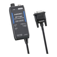
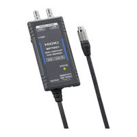
NON-CONTACT CAN SENSOR, CAN INTERFACE, SIGNAL PROBE
Brand:
Hioki
| Category:
Accessories
| Size: 2 MB
Table of Contents
Table of Contents
3
Introduction
5
About the Notations Used in this Manual
6
Verifying Package Contents
7
Options
9
Operating Precautions
11
Overview
13
Product Overview and Features
13
Part Names and Functions
14
SP7001/SP7002 Non-Contact CAN Sensor
14
SP7100 CAN Interface
15
SP7150 CAN Interface
16
SP9200 Signal Probe
17
SP9250 Signal Probe
17
LED Lighting/Flashing Specifications
18
Preparing before Use
19
Preparations
19
Connecting the Signal Probes
20
Connecting the Non-Contact CAN Sensor
21
Connecting the Ground Terminal
22
Connecting the CAN Interface
24
Supplying Power
25
Connecting the Signal Probes to the CAN Bus
26
When Using the SP9200
26
When Using the SP9250
28
Inspecting the Product before Use
29
Functionality
31
Switching the Non-Contact CAN Sensor's Signal Detection Sensitivity
31
Probe Setting Function (Automatic Polarity Selection)
32
Output Bus Error Detection Function
33
Specifications
35
SP7001/SP7002 Non-Contact CAN Sensor
35
SP7100 CAN Interface
38
SP7150 CAN Interface
41
SP9200 Signal Probe
44
SP9250 Signal Probe
45
SP9900 Split Cable (Dedicated Option for SP7100)
46
Maintenance and Service
47
Troubleshooting
49
CAN Signal Detection Is Unstable
49
You Are Unable to Detect CAN Signals Stably When Using the Product in an Environment Where It Is Exposed to Vibrations, for Example in Road Testing
50
Advertisement
Hioki SP7002 Instruction Manual (52 pages)
NON-CONTACT SENSOR, CAN INTERFACE, SIGNAL PROBE
Brand:
Hioki
| Category:
Accessories
| Size: 2 MB
Table of Contents
Table of Contents
3
Introduction
5
About the Notations Used in this Manual
6
Verifying Package Contents
7
Options
9
Operating Precautions
11
Overview
13
Product Overview and Features
13
Part Names and Functions
14
SP7001/SP7002 Non-Contact CAN Sensor
14
SP7100 CAN Interface
15
SP7150 CAN Interface
16
SP9200 Signal Probe
17
SP9250 Signal Probe
17
LED Lighting/Flashing Specifications
18
Preparing before Use
19
Preparations
19
Connecting the Signal Probes
20
Connecting the Non-Contact CAN Sensor
21
Connecting the Ground Terminal
22
Connecting the CAN Interface
24
Supplying Power
25
Connecting the Signal Probes to the CAN Bus
26
When Using the SP9200
26
When Using the SP9250
28
Inspecting the Product before Use
29
Functionality
31
Switching the Non-Contact CAN Sensor's Signal Detection Sensitivity
31
Probe Setting Function (Automatic Polarity Selection)
32
Output Bus Error Detection Function
33
Specifications
35
SP7001/SP7002 Non-Contact CAN Sensor
35
SP7100 CAN Interface
38
SP7150 CAN Interface
41
SP9200 Signal Probe
44
SP9250 Signal Probe
45
SP9900 Split Cable (Dedicated Option for SP7100)
46
Maintenance and Service
47
Troubleshooting
49
CAN Signal Detection Is Unstable
49
You Are Unable to Detect CAN Signals Stably When Using the Product in an Environment Where It Is Exposed to Vibrations, for Example in Road Testing
50
Hioki SP7002 Instruction Manual (44 pages)
NON-CONTACT CAN SENSOR
Brand:
Hioki
| Category:
Measuring Instruments
| Size: 1 MB
Table of Contents
Table of Contents
3
Introduction
5
About the Notations Used in this Manual
6
Verifying Package Contents
7
Options
8
Overview
11
Product Overview and Features
11
Part Names and Functions
12
SP7001/SP7002 Non-Contact CAN Sensor
12
SP7100 CAN Interface
13
SP9200 Signal Probe
14
LED Lighting/Flashing Specifications
15
Preparations
17
Preparing before Use
17
Connecting the SP9200 Signal Probes
18
Connecting the SP7001/SP7002 Non-Contact CAN Sensor
19
Connecting the Ground Terminal
20
Connecting the SP7100 CAN Interface
22
Supplying Power
23
Connecting the Signal Probes to the CAN Bus
24
Inspecting the Product before Use
26
Functionality
27
Switching the Non-Contact CAN Sensor's Signal Detection Sensitivity
27
Probe Setting Function (Automatic Polarity Selection)
28
Output Bus Error Detection Function
29
SP7001/SP7002 Non-Contact CAN Sensor
31
Specifications
31
SP7100 CAN Interface
34
SP9200 Signal Probe
37
SP9900 Split Cable (Option)
38
Maintenance and Service
39
Troubleshooting
41
Advertisement
Hioki SP7002 User Manual (2 pages)
Causes of “Output Bus Error Detection”
Brand:
Hioki
| Category:
Accessories
| Size: 0 MB
Table of Contents
Causes of 'Output Bus Error Detection'
1
Points
1
CASE 1: the Connected Device Outputs a CAN Signal
1
CASE 3: the Connected Device Is Sending an Error Frame
2
Cause 1: Incorrect Setting of the Connected Device
2
Make-Up of the CAN or CAN FD Frame
2
Advertisement
Related Products
Hioki SP7001
Hioki SP7100
Hioki SP9200
Hioki SM-8213
Hioki SM-8215
Hioki SM-8220
Hioki SM7420
Hioki Super megohm SM7110
Hioki Super megohm SM7120
Hioki SM-8216
Hioki Categories
Measuring Instruments
Test Equipment
Data Loggers
Multimeter
Accessories
More Hioki Manuals
Login
Sign In
OR
Sign in with Facebook
Sign in with Google
Upload manual
Upload from disk
Upload from URL