Page 1
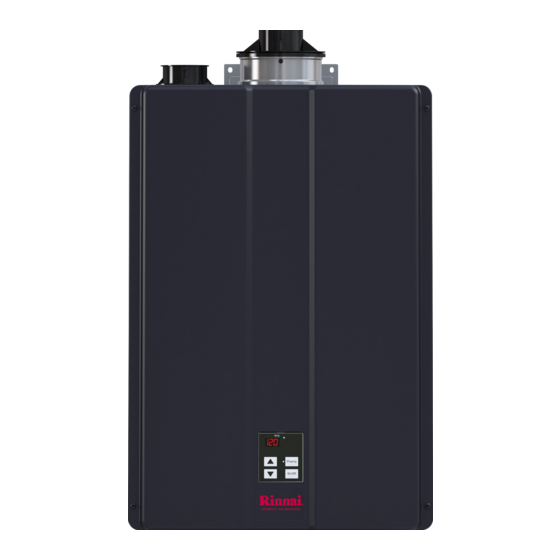
INTERNAL (INDOOR) MODELS: EXTERNAL (OUTDOOR) MODELS: CU199i (REU-N3237FFC-US) CU199e (REU-N3237WC-US) CU160i (REU-N2530FFC-US) CU160e (REU-N2530WC-US) ANSI Z21.10.3 ● CSA 4.3 Tankless Water Heater (Commercial) Installation and Operation Manual Place Model/Serial # Label Here Located in Manual Bag U334-0775X02(00) 06000012337594...
Page 2
– Si vous ne pouvez rejoindre le fournisseur, appelez le service des incendies. • L’installation et l’entretien doivent être assurés par un installateur ou un service d’entretien quali- fié ou par le fournisseur de gaz. Full-length French and Spanish versions available online at rinnai.us Rinnai Tankless Water Heater Installation and Operation Manual...
4.12 Configure Parameter Settings ..................... 65 4.13 External Pump with Circ-Logic ..................... 67 4.14 Post-Water Heater Installation Checklist ................68 Operation ............................70 Safety Precautions ........................70 Operating Instructions ......................72 Control Panel ........................73 Rinnai Tankless Water Heater Installation and Operation Manual...
Page 4
Massachusetts State Gas Regulations ................. 86 Wiring Diagram ........................88 Ladder Diagram ........................89 Pressure Drop and Water Flow Curves ................90 Guidelines for Additional Temperature Controllers ............... 91 Warranty ............................92 Rinnai Tankless Water Heater Installation and Operation Manual...
• When installation is complete, leave this manual with the water heater (for internal/ Natural Gas indoor units) or give the manual directly to the consumer. Polypropylene Pressure Relief Valve Pounds per square inch W.C. Inches water column Rinnai Tankless Water Heater Installation and Operation Manual...
• Les panneaux d’avertissement de ce man- uel sont ici pour éviter de vous blesser et d’autres personnes. Suivez- les explicite- ment. Rinnai Tankless Water Heater Installation and Operation Manual...
– Turn off the incoming water supply. This can be done at the isolation valve immediately below the water heater or by turning off the water supply to the building. Rinnai Tankless Water Heater Installation and Operation Manual...
Page 8
Flammable liquids should not be used or stored in the vicinity of this or any other gas appliance. Rinnai Tankless Water Heater Installation and Operation Manual...
3.2 Bottom View Pressure Relief Valve Cold Water Hot Water Inlet Outlet Figure 2: Bottom View Rinnai Tankless Water Heater Installation and Operation Manual...
Air Intake Air Inlet Filter Fan with Integrated Venturi Burner Assembly Gas Valve Ignition Unit Heat Exchanger Silencer PC Board Cover Water Flow Servo Control Panel Valve Integrated Pump Figure 3: Components Rinnai Tankless Water Heater Installation and Operation Manual...
0.4 GPM (1.5 L/min). The maximum gas supply pressure must not exceed the value specified by the manufacturer. Rinnai products are continually being updated and improved; therefore, specifications are subject to change without prior notice. Rinnai Tankless Water Heater Installation and Operation Manual...
3.6 Accessories Numerous optional accessories are available for purchase for your Rinnai Tankless Water Heater. Listed below are some commonly purchased accessories. For a complete list of accessories, visit www.rinnai.us. For questions, or to purchase an accessory, contact your local Rinnai dealer/distributor or Rinnai Customer Care at 1-800-621-9419.
Page 16
The DPS function provides domestic hot water priority for combination tankless water heater/ air handler applications. DPS/MIS Switch Part #: REU-OPU3 The MIS function provides tankless water heater monitoring via systems such as BMS (Building Management System). Rinnai Tankless Water Heater Installation and Operation Manual...
• The installation must conform with local codes or, in the absence of local codes, with the National Fuel Gas Code, ANSI Rinnai Tankless Water Heater Installation and Operation Manual...
• Isolation Valve Kit (for quick isolation of • Optional pipe cover the water heater for service and/or mainte- • PVC glue/cement and primer nance) • 2 conductor 22 AWG wire for controller • Literature Bag Rinnai Tankless Water Heater Installation and Operation Manual...
Scale build-up is caused by may contain these corrosive compounds. hard water and can be accelerated if the water heater is set at a high temperature. Rinnai offers Southeastern Filtration’s “ScaleCutter Water Conditioning System” that offers superior lime scale prevention and corrosion control.
Page 20
Chemi- cals that are corrosive in nature should not be stored or used near the water heater or vent termination. This requirement applies to internal (indoor) and external (outdoor) water heaters. Rinnai Tankless Water Heater Installation and Operation Manual...
Page 21
Supply Line Supply 1/2 in. Normally Open Solenoid Valve 1/2 in. Normally Open Solenoid Valve Line Route Drain Per Local Code Route Drain Per Local Code Figure 7: Freeze Protection Piping Diagram Rinnai Tankless Water Heater Installation and Operation Manual...
Page 22
Back 0 in. Sides (Left and Right) 2 in. (51 mm) Add 0.25 in. (6.35 mm) for recess box Vent 0 in. (Internal/Indoor Models) Front Exhaust 24 in. (610 mm) (External/Outdoor Models) Rinnai Tankless Water Heater Installation and Operation Manual...
Page 23
The installation must conform with local codes or, in the absence of local codes, with the National Fuel Gas Code, ANSI Z221.3/NFPA 54 Natural Gas and Propane , or the Installation Code, CSA B149.1 Rinnai Tankless Water Heater Installation and Operation Manual...
Use the appropriate screws for the wall construction to secure the mounting bracket to the wall between two studs. Figure 11: Mount the top bracket Figure 10: Secure the bracket Rinnai Tankless Water Heater Installation and Operation Manual...
Page 25
The water heater must be installed in an Bracket upright position. Do not install the water Figure 12: Mount the bottom bracket heater upside down or on its side. Figure 13: Mount the water heater Rinnai Tankless Water Heater Installation and Operation Manual...
• Refer to the PVC/CPVC manufacturer for appropriate fittings, solvents or joining methods. • The vent piece connected to the water heater must be secured with 1 self-tapping screw. • Refer to the instructions of the vent system Rinnai Tankless Water Heater Installation and Operation Manual...
Page 27
Figure 14: Vent Screen • Do not install the vent termination too close under the soffit where it could pres- ent recirculation of exhaust gases back into the combustion air part of the termina- tion. Rinnai Tankless Water Heater Installation and Operation Manual...
Page 28
Figure 19: Common Vent, Direct Vent Figure 20: Common Vent, Room Air Rinnai Tankless Water Heater Installation and Operation Manual...
Page 29
FGV Concentric Vent Kit (16 in. length) (Order from Rinnai) 196105, 197033 196105PVC FGV Concentric Vent Kit (16 in. length) (Order from Rinnai) 196125 196125PVC FGV Concentric Vent Kit (40 in. length) (Order from Rinnai) Rinnai Tankless Water Heater Installation and Operation Manual...
Page 30
2 in. x 4 in. Horizontal Termination 2PPS-HKL Kit-Concentric 190288 2 in. x 4 in. Concentric Horizontal Termination 190295 2 in. x 4 in. Concentric Vertical Termination 2 in. x 4 in. Concentric Horizontal CVENT-2 Termination Rinnai Tankless Water Heater Installation and Operation Manual...
Page 31
PVC/CPVC Concentric Vent Kit 3 in. x 32 in. 52CVKGVSF9003-32(CPVC) 52CVKGVS6503-44(PVC)/ PVC/CPVC Concentric Vent Kit 3 in. x 44 in. 52CVKGVSF9003-44(CPVC) Horizontal Termination Adapter SC03HT Vertical Termination Adapter SC03VT 3 in./5 in. Concentric Roof Termination PPs-UV ICRT3539 Rinnai Tankless Water Heater Installation and Operation Manual...
Page 32
3 in. x 5 in. Horizontal Termination Kit- 3PPS-HKL Concentric 3 in. x 5 in. Concentric 190388 Horizontal Termination 190395 3 in. x 5 in. Concentric Vertical Termination 3 in. x 5 in. Concentric CVENT-3 Horizontal Termination Rinnai Tankless Water Heater Installation and Operation Manual...
Page 33
FGV PVC Low Profile Termination Kit 196984PVC (Order from Rinnai) 081216 FGV PVC Wall Termination Kit 52SWVKGVS6502 PVC Side Wall Vent Kits 52WTVKGVS6502 PVC Wall Vent Kits HVENT-2 2 in. Low Profile Horizontal Vent Kit Rinnai Tankless Water Heater Installation and Operation Manual...
Page 34
FGV PVC Low Profile Termination Kit 196985PVC (Order from Rinnai) 081219 FGV PVC Wall Termination Kit 52SWVKGVS6503 PVC Side Wall Vent Kits 52WTVKGVS6503 PVC Wall Vent Kits HVENT-3 3 in. Low Profile Horizontal Vent Kit Rinnai Tankless Water Heater Installation and Operation Manual...
Page 35
Table 11: Approved Venting Materials By Manufacturer Manufacturer Vent Material Ubbink PVC (Outer Vent), Polypropylene (Inner Vent) Centrotherm Polypropylene Heat-Fab Metal Metal Fab Metal IPEX PVC/CPVC DuraVent Polypropylene Royal ECCO Manufacturing Polypropylene DiversiTech PVC/CPVC Rinnai Tankless Water Heater Installation and Operation Manual...
Page 36
[2] Permitted only if veranda, porch, deck, or balcony is fully open on a minimum of two sides beneath the floor. [3] If locally adopted installation codes specify clearances different than those illustrated, then the most stringent clearance shall prevail. Rinnai Tankless Water Heater Installation and Operation Manual...
Page 37
12 in. (0.30 m) Figure 22: Concentric Pipe Termination Clearances Figure 25: Between terminals at same level All terminations (horizontal and/or vertical) must terminate 12 in. (0.30 m) above grade or anticipated snow level. Rinnai Tankless Water Heater Installation and Operation Manual...
Page 38
1/4 in. per foot toward the appliance • 90° elbow is equivalent to 6 ft (2 m) according to the vent manufacturer’s installation instructions. Dispose of condensate per local codes. Rinnai Tankless Water Heater Installation and Operation Manual...
Page 39
12 in. 12 in. Intake 12 in. 12 in. 12 in. Minimum clearance for Ground/Grade/Snow Level Indicates area in which intake cannot be installed. Figure 33: Horizontal Vent and Combustion Air Piping Rinnai Tankless Water Heater Installation and Operation Manual...
Page 40
Secure the exhaust vent pipe to the exhaust adapter ring with the supplied screw. Exhaust Vent Pipe Supplied screw Figure 34 2. Remove and discard the combustion air vent cap. Figure 37 Figure 35 Rinnai Tankless Water Heater Installation and Operation Manual...
Page 41
2 in. (51 mm) 3 in. (76 mm) Vent Lengths 65 ft (20 m) 150 ft (46 m) • 45° elbow is equivalent to 3 ft (1 m) • 90° elbow is equivalent to 6 ft (2 m) Rinnai Tankless Water Heater Installation and Operation Manual...
Page 42
[3] If locally adopted installation codes specify clearances different than those illustrated, then the most stringent clearance shall prevail. Rinnai Tankless Water Heater Installation and Operation Manual...
Page 43
60 in. (1.52 m) vertically between terminals Corner Figure 39 Exhaust Termination Clearances for Internal (Indoor) Room Air Applications 12 in. 12 in. (0.30 m) 60 in. (1.52 m) vertically between terminals Corner Figure 40 Rinnai Tankless Water Heater Installation and Operation Manual...
Page 44
NOTE If ducts are used, the cross sectional area of the duct must be greater than or equal to the required free area of the openings to which they are connected. Rinnai Tankless Water Heater Installation and Operation Manual...
Page 45
Verify that adequate combustion air is available for all appliances installed in the space. □ Installation complies with National Fuel Gas Code, ANSI Z223.1/NFPA 54 as well as local and state regulations therein. Rinnai Tankless Water Heater Installation and Operation Manual...
Page 46
Exhaust Vent Pipe 5. Install the exhaust vent pipe. Ensure it is Supplied screw properly seated. Secure the exhaust vent pipe to the exhaust adapter ring with the supplied screw (Figure 46). Figure 46 Rinnai Tankless Water Heater Installation and Operation Manual...
Page 47
Vent Length 65 ft (20 m) 150 ft (46 m) 50 ft. (15 m) • 45° elbow is equivalent to 3 ft (1 m) • 90° elbow is equivalent to 6 ft (2 m) Rinnai Tankless Water Heater Installation and Operation Manual...
Page 48
3. Common Vent (Indoor Units Only. Direct Vent and Non-Direct/Room Air Vent) Common venting allows multiple Rinnai Tankless Water Heaters to share the same vent system. Rinnai water heaters can only be common vented with Schedule 40 PVC/CPVC or with the Rinnai certified common vent system.
Page 49
Common Vent Maximum Equivalent Vent Lengths (Rinnai Common Vent System or Schedule 40 PVC/CPVC) Common vent equivalent lengths include polypropylene pipe (PP) or PVC in a back-to-back or inline configuration. For the table below: Vent Length Header • Header is the main vent pipe into which several vents connect.
Page 50
Common Vent Terminations Table 21: Various 3 in., 4 in., and 6 in. Schedule 40 PVC/CPVC Terminations Product Diagram Description 90° Elbow 45° Elbow Table 22: Rinnai Common Vent Terminations (Ubbink C-Vent) Manufacturer Phone Web Site Ubbink 800-621-9419 www.rinnai.us Part Number...
Page 51
Short Sweep Close Turn and vent length. Condensate trap must include a loop that can hold 6 in. (15 cm) of water. Refer to the Rinnai Common Vent Installation manual for more information. Rinnai Tankless Water Heater Installation and Operation Manual...
Page 52
5. Proceed to “Programing Cascade Accessory Port Communication” on the following page. Location Figure 53 Primary Secondary 1 Secondary 2 Cascade Jumper Cascade Jumper Figure 54 Rinnai Tankless Water Heater Installation and Operation Manual...
Page 53
When ID setting is successful, the controller display will change from “- - -” to the newly set ID number. Secondary 01 Secondary 02 Secondary 03 Primary water heater Identify Secondary ID by Figure 55 pressing “On/Off” Rinnai Tankless Water Heater Installation and Operation Manual...
Valve Boiler Drain Valve accordance with all local building codes. Confer with local building Figure 56 essure Relief Valve Solenoid Valve officials before installation. Rinnai Tankless Water Heater Installation and Operation Manual...
7. Ensure that both Drain Valves are in the closed position before turning on water supply. Hot Outlet Cold Inlet Swivel Nut (Integrated Gasket) Drain Valve Hot Isolation Valve Cold Isolation Valve (Red) (Blue) Figure 57 Rinnai Tankless Water Heater Installation and Operation Manual...
Con- tact the water supplier or local plumbing inspector on how to correct this situation. Do not plug the pressure relief valve. Rinnai Tankless Water Heater Installation and Operation Manual...
Page 57
Figure 58 IMPORTANT • Do not use pipe dope or thread sealant on union fitting with gasket. • Be careful not to lose or throw away the gasket. Rinnai Tankless Water Heater Installation and Operation Manual...
Pipe open to wall. atmosphere • If a floor drain is not available or the drain is above the level of the condensate drain, a condensate pump should be installed. Condensate Pump Figure 60 Rinnai Tankless Water Heater Installation and Operation Manual...
Page 59
5. Turn off the water heater by pressing the “On/ white wires labeled “To Condensate Pump Off” button on the controller. Wait five seconds Safety Switch.” then turn the power back on. This will clear the diagnostic code. Rinnai Tankless Water Heater Installation and Operation Manual...
Page 60
* Safety switch wires connect to the NO and COM contacts on the safety switch. • NO - Normally Open • NC - Normally Closed • COM - Common (Neutral) Figure 63 Rinnai Tankless Water Heater Installation and Operation Manual...
Rinnai Tankless Water Heater Installation and Operation Manual...
Page 62
Answer: 70 (21) (CFH) = 80 (24) For this example, the pipe diameter 90 (27) must be at least 3/4 in. pipe size and 10 ft (3 m) in length. 100 (30) Rinnai Tankless Water Heater Installation and Operation Manual...
Page 63
60 (18) Total Gas 80 (24) 264,000 Btu/hr Input 100 (30) For this example, the pipe diameter must be at least 1/2 in. nominal pipe size and 10 ft (3 m) in length. Rinnai Tankless Water Heater Installation and Operation Manual...
Confirm that the electricity is supplied from 120 VAC, 60 Hz power source and is in a properly grounded circuit. □ Confirm that an extension cord or an adapter plug has NOT been used with the water heater. Rinnai Tankless Water Heater Installation and Operation Manual...
0 1 A Example: Display will change from 01A to 01b for Maximum Temperature setting (as shown below). 6. To exit the parameters, press the “A” button for 1 second. Figure 68 Rinnai Tankless Water Heater Installation and Operation Manual...
Page 66
NOTE: Service Soon (55) will display • Service Soon will appear again based on the selected on the controller again when the water service interval. heater reaches the interval selected in the parameter settings. Rinnai Tankless Water Heater Installation and Operation Manual...
4. 1 3 External Pump with Circ-Logic Rinnai SENSEI™ Tankless Water Heaters include Circ-Logic technology that offers the comfort and convenience of instant hot water with the use of an external recirculation pump. Circ-Logic controls the on/off sequence and operation cycles of the external recirculation pump through the programming of the tankless water heater’s parameter settings.
YES to each question. If you answer NO to any question, installation is not complete. Refer to the applicable section in the Rinnai Tankless Water Heater Installation and Operation Manual for additional information. For assistance, contact your local dealer or distributor, or call Rinnai Customer Care at 1-800-621-9419. INSTALLATION LOCATION YES NO □...
Page 69
Did you install a manual gas control valve in the gas line to the water heater? □ □ Is the inlet gas pressure within limits? □ □ Did you purge the gas line of any debris before connecting the water heater? Rinnai Tankless Water Heater Installation and Operation Manual...
Follow the gas supplier’s instructions. – If you cannot reach your gas supplier, call the fire department. • Installation and service must be performed by a qualified installer, service agency or the gas supplier. Rinnai Tankless Water Heater Installation and Operation Manual...
Page 71
Control System” that offers superior lime scale prevention and corrosion control by feeding a blend of control compounds into the water supply. Damage and repair due to corrosive compounds in the air is not covered by warranty. Rinnai Tankless Water Heater Installation and Operation Manual...
3. Turn the manual gas control valve located at gas inlet of appliance clockwise to the OFF 2. Turn off all electric power to the appliance if position. service is to be performed. Rinnai Tankless Water Heater Installation and Operation Manual...
(Up) and (Down) buttons at the same time until a beep is heard (approximately 3 seconds). Then, release both buttons. To turn on the beeps, repeat the above steps. Figure 72 Rinnai Tankless Water Heater Installation and Operation Manual...
• 20 seconds at 130°F (54°C) • 8 minutes at 120°F (49°C) Children, disabled, or elderly are at highest risk of being scalded. Feel water before bathing or showering. Figure 74 Rinnai Tankless Water Heater Installation and Operation Manual...
3. Use the (Up) and (Down) buttons to scroll to the desired information described in the Performance Data Table. Figure 76 4. To exit performance data, repeat step 2 above. 5. When complete, the set temperature appears in the display. Figure 77 Rinnai Tankless Water Heater Installation and Operation Manual...
Page 76
(Outdoor Units Only) Pump Hours x100 Hours Pump Cycles Exhaust Temperature °F * Refer to the Technical Data Sheet located on the inside front cover of the water heater for additional information. Rinnai Tankless Water Heater Installation and Operation Manual...
* See “Electrical Diagnostics” on Technical Data or damage to the heat exchanger. Sheet located on inside front cover of water heater. • Ensure it is not in forced Hi setting. Rinnai Tankless Water Heater Installation and Operation Manual...
Page 78
Follow the steps above for Code 38 for Contact a licensed professional to troubleshooting. service the appliance. PC Board * See “Electrical Diagnostics” on Technical Data Sheet located on inside front cover of water heater. • Replace PC Board Rinnai Tankless Water Heater Installation and Operation Manual...
Page 79
To reset the SS code, push the On/Off button on the temperature controller 5 times in 5 seconds. * See “Electrical Diagnostics” on Technical Data Sheet located on inside front cover of water heater. Rinnai Tankless Water Heater Installation and Operation Manual...
The vent system should be inspected for blockages including snow or other debris or damage. If the vent is blocked and cannot be easily cleared, contact a trained and qualified professional. Rinnai Tankless Water Heater Installation and Operation Manual...
Page 81
(shut-off)t valves. Put a bucket under the filter Blue Flame at the bottom of the water heater to catch Figure 79 any water that is contained inside the unit. Unscrew the water filter. Rinse the filter to Rinnai Tankless Water Heater Installation and Operation Manual...
• If the air filter appears to have lint and/or dust build up, follow the cleaning procedure described below. • If the air filter appears damaged, contact a trained and qualified professional for a replacement air filter assembly. Rinnai Tankless Water Heater Installation and Operation Manual...
Page 83
• Inspect the air filter for any debris that may restrict air flow to the water heater. • If the filter still appears dirty repeat the cleaning steps. • Replace the air filter. 6. Power ON the water heater. Rinnai Tankless Water Heater Installation and Operation Manual...
Damage caused by lime build-up is 13. Restore electrical power to the water heater. not covered by the water heater’s warranty. Rinnai strongly recommends installation of isolation NOTE valves to allow for flushing of the heat exchanger.
Valve 6. Connect power to the water heater. 7. After confirming that the temperature controller Figure 84: Piping Diagram is off, turn on the gas supply. 8. Turn on the temperature controller. Rinnai Tankless Water Heater Installation and Operation Manual...
In with the provisions of 248 CMR 5.08(2)(a)1 addition, the installing plumber or gas fitter through 4. shall observe that a battery operated or hard Rinnai Tankless Water Heater Installation and Operation Manual...
Page 87
COMBINATION SPACE HEATING/POTABLE WATER SYSTEM (For Use In Commonwealth of Massachusetts) Rinnai Tankless Water Heater Installation and Operation Manual...
Water Flow (GPM) Figure 88 The chart below applies only to incoming water temperatures of 70°F (21°C) or less. For incoming water temperatures greater than 70°F (21°C), please contact Rinnai. NOTE: Maximum flow rates may vary based CU199 on set temperature, Delta T and altitude.
Connect controller cable to perature controller can be adjusted by the mating terminal at bottom public. right side of PC Board. Wiring illustration (Detailed wiring instructions included with temperature Figure 91 controller package) Rinnai Tankless Water Heater Installation and Operation Manual...
Rinnai’s sole discretion. The warranty claim for product parts and labor may be denied if a component or product returned to Rinnai is found to be free of defects in material or workmanship; damaged by improper installation, use or operation; or damaged during return shipping.
Page 93
Limitation on Warranties No one is authorized to make any other warranties on behalf of Rinnai America Corporation. Except as expressly provided herein, there are no other warranties, expressed or implied, including, but not limited to warranties of merchantability or fitness for a particular purpose, which extend beyond the description of the warranty herein.
Page 94
Notes Notes Rinnai Tankless Water Heater Installation and Operation Manual...
Page 95
Notes Notes Rinnai Tankless Water Heater Installation and Operation Manual...
Page 96
Rinnai America Corporation 103 International Drive Peachtree City, GA 30269 Tel: 1-800-621-9419 Web: rinnai.us 100000504(06) rinnai.ca 6/2020...