Rinnai RU199i, RU180i, RU160i, RU130i, CU199i Manual
- Installation and operation manual (92 pages) ,
- Installation instructions manual (25 pages) ,
- Service presentation (120 pages)
Advertisement
- 1 Welcome
- 2 About the Common Venting System
- 3 3 in. Common Venting
- 4 4 in. Common Venting
- 5 6 in. Common Venting
- 6 Common Vent Terminations
- 7 Sample Horizontal Termination Assembly
- 8 Sample Vertical Termination Assembly-Room Air
- 9 Maintenance Clearances
- 10 Combustion Air Requirements
- 11 Exhaust Vent Termination Clearances
- 12 Additional Clearances
- 13 Installation Instructions (Condensate Trap and Drain Pipe)
- 14 Final Checklist
- 15 Safety
- 16 Documents / Resources
Welcome
This manual provides installation instructions for PVC/CPVC common venting and is a supplement to the Installation and Operations Manual supplied with the Rinnai Tankless Water Heater. For Ubbink Polypropylene (PP) common venting, refer to installation instructions for Ubbink Polypropylene (PP) common venting.
Common venting must satisfy all the requirements of the Installation and Operations Manual, as well as the requirements in this manual.
For detailed information on the Rinnai Tankless Water Heater, including installation instructions, refer to the Tankless Water Heater Installation and Operation Manual or view an online version at rinnai.us.
Illustrations of tankless water heaters in this document represent one of the applicable Rinnai tankless water heaters. Your water heater may look different than the images in this document.


If the information in these instructions is not followed exactly, a fire or explosion may result causing property damage, personal injury or death.
- Do not store or use gasoline or other flammable vapors and liquids in the vicinity of this or any other appliance.
- WHAT TO DO IF YOU SMELL GAS
- Do not try to light any appliance.
- Do not touch any electrical switch; do not use any phone in your building.
- Immediately call your gas supplier from a neighbor's phone. Follow the gas supplier's instructions.
- If you cannot reach your gas supplier, call the fire department.
- Installation and service must be performed by a licensed professional.
To The Installer
- This manual is intended for the trained and qualified professional and is designed for licensed installers who should have skills such as:
- Gas sizing
- Connecting gas lines, water lines, valves, and electricity
- Knowledge of applicable national, state, and local codes
- Installing venting through a wall or roof
- Training in installation of tankless water heaters. Training on Rinnai Tankless Water Heaters is accessible at rinnaipro.myabsorb.com.
- A trained and qualified professional must test the Common Venting System for leaks before use.
- The installation must conform to the Rinnai Tankless Water Heater Installation and Operation Manual that is shipped with the unit, local codes, or in the absence of local codes, with the National Fuel Gas Code, ANSI Z223.1/NFPA 54.
- Read all instructions contained in this manual before installing the Common Venting System.
- Proper installation is the responsibility of the installer.
- When installation is complete, give all manuals related to the common venting installation (including this manual and the Rinnai Tankless Water Heater Installation and Operation Manual) directly to the consumer. The manuals should be stored in a readily accessible location for future reference.
To The Consumer
- Keep this manual for future reference.
- Be sure your Common Venting System is installed by a trained and qualified professional.
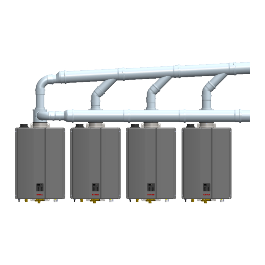
About the Common Venting System
Common venting allows multiple Rinnai Tankless Water Heaters to share the same vent system.
Rinnai Tankless Water Heaters can only be common vented with Schedule 40 PVC/CPVC or with a Rinnai certified common vent system.

Venting Guidelines
- Use only the materials listed in this manual for vent, air intake pipe, and fittings. Failure to comply with this warning could result in property damage, personal injury, or death.
- When cutting vent components, ensure that the cuts are straight.
- Chamfer and deburr all edges before installing the components.
- Vent joints must not leak. Confirm gas tight connections of every vent joint.
- Before operating the water heater(s), ensure vent system is clean and free of debris.
- Vent system must be supported according to the vent manufacturer's installation instructions.
- Venting should be as direct as possible with a minimum number of fittings.
- The common vent system must only be installed by a trained and qualified professional.
Common Vent Termination Clearances
- Vent termination per ANSI Z223.1/NFPA 54. For clearances not specified in ANSI Z223.1/NFPA 54, clearances are in accordance with local installation codes and the requirements of the gas supplier.
- DO NOT slope the combustion air pipe toward unit. Failure to comply with this warning could result in property damage, personal injury, or death.
- DO NOT apply PVC/CPVC glues, solvents, or cleaners to the tankless water heater's intake or exhaust gasket connections. Failure to correctly assemble the components according to these instructions may result in property damage, personal injury, or death.
Do Not
- Do not exceed the maximum number of units indicated in the Rinnai Tankless Water Heater Installation and Operation Manual.
- Do not use cellular core PVC/CPVC, Radel, ABS or galvanized material for the exhaust vent.
- Do not combine vent components from different manufacturers.
- Do not connect the venting system with an existing vent or chimney.
- Do not cover vent components with thermal insulation.
- Do not common vent with the vent pipe of any other type of water heater or appliance.
- Do not reduce vent diameter to less than 2 in. (51 mm).
- Do not install the water heater in an area of negative pressure.
- Do not install the water heater, venting, and vent termination(s) in any areas where the air may contain corrosive compounds.
Must Do
- You must use vent components that are certified and listed with the water heater model.
- The vent system must vent directly to the outside of the building and use outside air or room air for combustion.
- Avoid dips or sags in horizontal vent runs by installing supports per the vent manufacturer's instructions.
- Support horizontal vent runs a minimum of every four feet and all vertical vent runs a minimum of every six feet.
- Venting should be as direct as possible with a minimum number of pipe fittings.
- Vent components connected to the water heater must be secured with one self-tapping screw. Do not use any glues or solvents to connect vent components to the water heater.
- Set the temperature setting on all water heaters being common vented to the same temperature.
Schedule 40 PVC/CPVC Common Vent Guidelines
PVC solvents (primer and glue) can be extremely flammable. Vapors may cause a flash fire or explosion resulting in property damage, personal injury or death.
- Keep solvents away from heat, sparks, flames and all other sources of ignition.
- Do not solder, cut or weld until all vapors have dissipated.
- PVC solvents are heavier than air causing them to settle at low points of the system.
- Before using PVC solvent:
- Disconnect power to the water heater.
- Remove the front cover of the water heater.
- Ensure areas around the water heater and PVC venting are well ventilated.
- Allow all vapors to dissipate before applying power to the system or introducing any other source of ignition.
When installing PVC/CPVC Common Vent, follow these guidelines:

- Avoid sharp bends or tees in the vent system.
These vent components create additional restrictions that could reduce performance of the water heaters. - PVC combustion air and exhaust should terminate with elbow or tee pointing down.
This will stop unwanted moisture from entering the vent system. - Fire rated penetrations shall be fire stopped.
Contact your vent supplier or local fire stop manufacturer for appropriate fire stop methods. - Examine all vent components for damage prior to installation.
- PVC/CPVC vent systems must be free to expand and contract. Refer to the vent manufacturer's installation instructions for appropriate support methods.
- PVC/CPVC venting must include unrestricted vent movement through walls, ceilings, and roof penetrations.
- Use only PVC/CPVC primer and cement approved for use by the vent manufacturer.
- Refer to vent manufacturer's installation instructions for proper joint assembly procedures and products.
- PVC/CPVC common venting should include a condensate drain and trap between the header and vent length. Condensate trap must include a loop that can hold 6 in. (15 cm) of water. See "PVC/CPVC Common Vent Installation" illustration on this page.
- Multi-story common venting system is prohibited.
DO NOT
- DO NOT mix vent pipe, fittings or joining methods from different vent manufacturers.
- DO NOT attempt to repair damaged vent. Damaged vent components must be replaced.
- DO NOT use short radius elbows in the common vent system.
| ACCEPTABLE | ACCEPTABLE | NOT ACCEPTABLE |
| 90° Elbows, Long Sweep | 90° Elbows, Short Sweep | 90° Elbows, Close Turn |
 |  |  |
 NOTE
NOTE
Unless recovering a tank, Rinnai recommends electronically connecting with common venting and where water heaters are in a manifold system. Refer to the Rinnai Tankless Water Heater Installation and Operation Manual for additional details on electronically connecting multiple water heaters.
High Altitude Installations
- High altitude installations are certified up to 10,200 ft (3,109 m).
- Reference the respective Rinnai Tankless Water Heater Installation and Operation Manual to set the water heater up for the altitude at which they will be operating.
- Tankless water heaters using common venting at altitudes over 2,000 ft (610 m) will automatically derate.
Common Vent Maximum Equivalent Vent Lengths
For the table below:
- Header is the main vent pipe into which several vents connect.
- Vent Length is the distance from the end of the header to the vent termination.
- Maximum vent length starts at the end of the header system.
- Use 10 ft (3 m) as equivalent vent length for 90° elbows.
- For use with SENSEI™ internal (indoor) tankless water heaters.


Common Vent Maximum Equivalent Vent Length / Rinnai Common Vent System or Schedule 40 PVC/CPVC

3 in. Common Venting
Direct Vent

Room Air
- Refer to the "Combustion Air Requirements" section of this manual for room air requirements.


4 in. Common Venting
Direct Vent
- Maximum 4 Units


Room Air
- Maximum 4 Units
- Refer to the "Combustion Air Requirements" section of this manual for room air requirements.


6 in. Common Venting
Direct Vent
- Maximum 12 Units


Room Air
- Maximum 12 Units
- Refer to the "Combustion Air Requirements" section of this manual for room air requirements.


Common Vent Terminations
Various 3 in., 4 in., and 6 in. Schedule 40 PVC/CPVC Terminations:

Sample Horizontal Termination Assembly
Support Brackets Required

NOTE
Vent termination per ANSI Z223.1/NFPA 54. For clearances not specified in ANSI Z223.1/NFPA 54, clearances are in accordance with local installation codes and the requirements of the gas supplier.
Sample Vertical Termination Assembly-Room Air
Support Brackets Required

Maintenance Clearances
If the vent system is to be enclosed, it is suggested that the design of the enclosure shall permit inspection of the vent system. The design of such an enclosure shall be deemed acceptable by the installer or the local inspector.
Water Heater Clearances
Refer to the Rinnai Tankless Water Heater Installation and Operation Manual for minimum clearance requirements around the water heater.
Vertical Termination Clearances (All System Sizes)
There should be a minimum of 12 in. (305 mm) between exhaust and intake terminations.
Clearances of Brackets:
All supports, such as wall brackets or spacer blocks, must be installed with a maximum distance of 78 in. (2 m) between each support. Additional supports can be installed before and after an elbow if needed.
Freestanding Components:
Components which are installed freestanding for vertical termination with a length of over 59 in. (1.5 m), must be additionally secured to the building with guys or braces.
Pitched Roof Termination Clearances:
")
NOTE
Vent termination per ANSI Z223.1/NFPA 54. For clearances not specified in ANSI Z223.1/NFPA 54, clearances are in accordance with local installation codes and the requirements of the gas supplier.
Horizontal Termination Clearances
This appliance, along with the Common Vent System, is certified with the 3 in., 4 in., 6 in. wall termination mounted in the orientation shown below.

| Vent Size | Separation Distance |
| 3 in., 4 in., 6 in. | 12 in. Minimum |
The exhaust and combustion air terminations must follow these clearances:
- 12 in. minimum vertically from bottom of combustion air termination to ground or anticipated snow line.
- 12 in. minimum from edge of exhaust termination to edge of combustion air termination.
There should be a minimum of 36 in. (91 cm) between exhaust terminations in multiple common vent installations. Refer to the Rinnai Tankless Water Heater Installation and Operation Manual for maximum vent lengths based on the vent diameter installed.

Combustion Air Requirements
Common Vent Applications Utilizing Room Air

This rack system requires adequate combustion air for ventilation and dilution of flue gases. Failure to provide adequate combustion air can result in unit failure, fire, explosion, serious bodily injury or death. Use the following methods to ensure adequate combustion air is available for correct and safe operation of this rack system.

Combustion air must be free of corrosive chemicals. Do not provide combustion air from corrosive environments. System failure due to corrosive air is not covered by warranty.
Combustion air must be free of acid forming chemicals such as sulfur, fluorine and chlorine. These chemicals have been found to cause rapid damage and decay and can become toxic when used as combustion air in gas appliances. Such chemicals can be found in, but not limited to bleach, ammonia, cat litter, aerosol sprays, cleaning solvents, varnish, paint, and air fresheners. Do not store these products or similar products in the vicinity of the water heater system.
Unconfined Space:
An unconfined space is defined in National Fuel Gas Code, ANSI Z223.1/NFPA 54 as "a space whose volume is not less than 50 cubic feet per 1,000 Btu/hr (4.8 m3 per kW per hour) of the aggregate input rating of all appliances installed in that space. Rooms communicating directly with the space in which the appliances are installed, through openings not furnished with doors, are considered a part of the unconfined space." If the "unconfined space" containing the system is in a building with tight construction, additional outside air may be required for proper operation. Outside air openings should be sized the same as for a confined space.
Confined Space:
(Small Room, Closet, Alcove, Utility Room, Etc.)
A confined space is defined in the National Fuel Gas Code, ANSI Z223.1/NFPA 54 as "a space whose volume is less than 50 cubic feet per 1,000 Btu/hr (4.8 m3 per kW per hour) of the aggregate input rating of the combined appliances installed in that space." A confined space must have two combustion air openings. Size the combustion air openings based on the BTU input for all gas utilization equipment in the space and the method by which combustion air is supplied.
Louvers and Grills
When sizing the permanent opening, consideration must be taken for the design of the louvers or grills to maintain the free area required for all gas utilizing equipment in the space. If the free area of the louver or grill design is not available, assume wood louvers will have 25% free area and metal louvers or grills will have 75% free area. Under no circumstance should the louver, grill or screen have openings smaller than 1/4 in.
Example:
Wood: 10 in x 12 in x 0.25 = 30 in2
Metal: 10 in x 12 in x 0.75 = 90 in2

Location
To maintain proper circulation of combustion air, two permanent openings (one upper, one lower) must be positioned in confined spaces. The upper shall be within 12 in. (305 mm) of the top of the confined space and the lower opening shall be within 12 in. (305 mm) of the bottom of the confined space. Openings must be positioned as to never be obstructed.
Using Outdoor Air For Combustion
Outdoor air can be provided to a confined space through two permanent openings, one commencing within 12 in. (305 mm) of the top and one commencing within 12 in. (305 mm) of the bottom of the confined space. The openings shall communicate to the outside by one of two ways.

(Be sure to maintain 12 in. (305 mm) above grade or anticipated snow level)
Vent termination per ANSI Z223.1/NFPA 54. For clearances not specified in ANSI Z223.1/NFPA 54, clearances are in accordance with local installation codes and the requirements of the gas supplier.

(Be sure to maintain 12 in. (305 mm) above grade or anticipated snow level)
NOTE
Combustion air provided to the system should not be taken from any area of the structure that may produce a negative pressure (such as exhaust fans or powered ventilation fans).
Using Indoor Air For Combustion
When using air from other room(s) in the building, the total volume of the room(s) must be of adequate volume (greater than 50 cubic feet per 1,000 Btu/hr). Each combustion air opening must have at least one square inch of free area for each 1,000 Btu/hr, but not less than 100 square inches each.
When communicating directly with the outdoors through horizontal ducts, each opening shall have a minimum free area of 1 in 2 /2,000 Btu/hr (1,100 mm 2 /kW) of total input rating of all appliances in the confined space.
Note: If ducts are used, the cross sectional area of the duct must be greater than or equal to the required free area of the openings to which they are connected.
When communicating indirectly with the outdoors through vertical ducts, each opening shall have a minimum free area of 1 in 2 /4,000 Btu/hr (550 mm of total input rating of all appliances in the confined space. Combustion air to the appliance can be provided from a well ventilated attic or crawl space.
TO PREVENT POSSIBLE PERSONAL INJURY OR DEATH DUE TO ASPHYXIATION, COMMON VENTING WITH OTHER MANUFACTURER'S INDUCED DRAFT APPLIANCES IS NOT ALLOWED.
Checklist for Combustion Air and Venting Requirements
- Verify proper clearances around the vents.
- Ensure that the "Combustion Air Requirements" are followed that will provide sufficient combustion air for the appliance.
- Ensure approved venting components have been used.
- All horizontal vent runs must be sloped up away from the water heater a minimum of 1/4 in. per foot (21 mm per meter).
- Verify that there is adequate combustion air.
- The installation conforms with local codes or, in the absence of local codes, with the National Fuel Gas Code, ANSI Z223.1/NFPA 54, and/or the CSA B149.1, Natural Gas and Propane Installation Code (Current Editions), local codes, and the manufacturer's instructions.
Exhaust Vent Termination Clearances
The information below applies to Concentric and Twin Pipe:

1 In accordance with the current CSA B149.1, Natural Gas and Propane Installation Code.
2 In accordance with the current ANSI Z223.1/NFPA 54, National Fuel Gas Code.
If locally adopted installation codes specify clearances different than those illustrated, then the most stringent clearance shall prevail.
| Clearance to opposite wall is 24 in. (60 cm). | |
| [1] A vent shall not terminate directly above a sidewalk or paved driveway that is located between two single family dwellings and serves both dwellings. [2] Permitted only if veranda, porch, deck, or balcony is fully open on a minimum of two sides beneath the floor. | *Clearances are in accordance with local installation codes and the requirements of the gas supplier. |
Other than direct vent, when using room air for combustion, you must install terminations to expel exhaust.
Room Air and External Termination Clearances

1 In accordance with the current CSA B149.1, Natural Gas and Propane Installation Code.
2 In accordance with the current ANSI Z223.1/NFPA 54, National Fuel Gas Code.
If locally adopted installation codes specify clearances different than those illustrated, then the most stringent clearance shall prevail.
| Clearance to opposite wall is 24 in (60 cm). | |
| [1] A vent shall not terminate directly above a sidewalk or paved driveway that is located between two single family dwellings and serves both dwellings. [2] Permitted only if veranda, porch, deck, or balcony is fully open on a minimum of two sides beneath the floor. | *Clearances are in accordance with local installation codes and the requirements of the gas supplier. |
Additional Clearances
Check on whether local codes supersede the clearances below.

- Avoid termination locations near a dryer vent.
- Avoid termination locations near commercial cooking exhaust.
- You must install a vent termination at least 12 in. (305 mm) above grade or snow line.
The vent for this appliance shall not terminate
- Over public walkways.
- Near soffit vents or crawl space vents or other areas where condensate or vapor could create a nuisance or hazard or cause property damage.
- Where condensate or vapor could cause damage or could be detrimental to the operation of regulators, relief valves, or other equipment.
Important considerations for locating vent termination under a soffit (ventilated or unventilated or eave vent; or to a deck or porch)
- Do not install vent termination under a soffit vent where exhaust can enter the soffit vent.
- Install vent termination so that exhaust and rising moisture will not collect under eaves. Discoloration to the exterior of the building could occur if installed too close.
- Do not install the vent termination too close under the soffit where it could present recirculation of exhaust gases back into the combustion air intake part of the termination.
 Represents the exhaust vent of the common venting.
 Represents the combustion air vent of the common venting.

Installation Instructions (Condensate Trap and Drain Pipe)
Install the Condensate Trap and Drain Pipe
")
Condensate must be drained to prevent malfunction, diagnostic code failures, or property damage. Condensate should be disposed according to local codes. Refer to the National Fuel Gas Code, ANSI Z223.1/NFPA 54, or the Natural Gas and Propane Installation Code, CSA B149.1 condensate disposal.
A condensate pump must be used if the condensate outlet is lower than the public sewage system.
Rinnai recommends installing a condensate neutralizer which allows condensate to flow through neutralizing media to raise the pH of the condensate to a level that will help prevent corrosion of the drain and public sewer system.
Ensure that the condensate drain does not freeze.
Final Checklist
- Reference the Rinnai Tankless Water Heater Installation and Operation Manual for proper installation of the Rinnai tankless water heaters.
- Clearances from the water heater unit are met.
- Clearances from the exhaust termination(s) and the combustion air termination(s) are met.
- Ensure you have used the correct venting products and that you have completely followed the venting manufacturer's installation instructions and these installation instructions.
- Verify that the vent system does not exceed the maximum equivalent length allowed.
- Explain to the customer the importance of not blocking the vent termination or air intake.
- Explain to the customer the operation of the water heater, safety guidelines, maintenance, and warranty.
- The installation conforms with local codes or, in the absence of local codes, with the National Fuel Gas Code, ANSI Z223.1/NFPA 54, and/or the CSA
- B149.1, Natural Gas and Propane Installation Code (Current Editions), local codes, and the manufacturer's instructions.
- Inform the consumer if the isolation valves are not installed or if a water softening system is not installed.
- Verify that the water heaters installed match the model numbers described in the manual.
- Verify that the appropriate amount of combustion air has been provided.
- Verify the parameter setting has been adjusted for the altitude/elevation of the installation location.
- Leave this manual taped to one of the water heaters or give the entire manual directly to the consumer.
Safety
READ ALL INSTRUCTIONS BEFORE INSTALLATION
If the information in these instructions is not followed exactly, a fire or explosion may result causing property damage, personal injury, or death.
- Do not store or use gasoline or other flammable vapors and liquids in the vicinity of this or any other appliance.
- WHAT TO DO IF YOU SMELL GAS
- Do not try to light any appliance.
- Do not touch any electrical switch; do not use any phone in your building.
- Immediately call your gas supplier from a neighbor's phone. Follow the gas supplier's instructions.
- If you cannot reach your gas supplier, call the fire department.
- Installation and service must be performed by a trained and qualified installer, service agency or the gas supplier.
- The warning signs in this manual are here to prevent injury to you and others. Please follow them explicitly.
- Installations must comply with local requirements and with the National Fuel Gas Code, ANSI Z223.1/NFPA 54 for U.S. installations.
- Use only the materials listed in this manual for vent, air intake pipe, and fittings. Failure to comply with this warning could result in property damage.
- DO NOT slope the combustion air pipe toward unit. Failure to comply with this warning could result in property damage, personal injury, or death.
- DO NOT apply PVC/CPVC glues, solvents, or cleaners to the tankless water heater's intake or exhaust gasket connections. Failure to correctly assemble the components according to these instructions and the Rinnai water heater installation and operation manual may result in property damage, personal injury, or death.
Safety Symbols
This manual contains the following important safety symbols. Always read and obey all safety messages.
Safety alert symbol. Alerts you to potential hazards that can kill or hurt you and others.

Indicates an imminently hazardous situation which, if not avoided, will result in personal injury or death.
Indicates a potentially hazardous situation which, if not avoided, could result in personal injury or death.

Indicates a potentially hazardous situation which, if not avoided, could result in minor or moderate injury. It may also be used to alert against unsafe practices.
Documents / Resources
References
Download manual
Here you can download full pdf version of manual, it may contain additional safety instructions, warranty information, FCC rules, etc.
Download Rinnai RU199i, RU180i, RU160i, RU130i, CU199i Manual
Advertisement


Need help?
Do you have a question about the RU199i and is the answer not in the manual?
Questions and answers