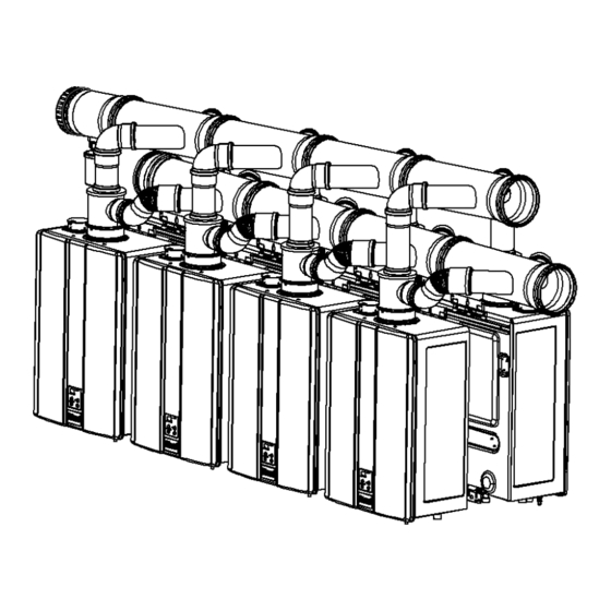
Page 1
WARNING If the information in these instructions is not followed exactly, a fire or explosion may result causing property damage, personal injury or death. Do not store or use gasoline or other flammable vapors and liquids in the vicinity of this or any other —...
Page 2
This manual provides installation instructions for Ubbink Polypropylene (PP) common venting and is a supplement to the Installation and Operations Manual supplied with the Rinnai Tankless Water Heater. For • Keep this manual for future reference. PVC/CPVC common venting, refer to installation •...
Page 3
DO NOT apply PVC/CPVC glues, solvents, or cleaners to the tankless water heater’s intake or exhaust gasket connections. Failure to correctly assemble the components according to these instructions and the Rinnai water heater installation and operation manual may result in property damage, personal injury, or death.
Page 4
You must use vent components that are certified Do not exceed the maximum number of units indicated and listed with the water heater model. in the Rinnai Tankless Water Heater Installation and • The vent system must vent directly to the outside Operation Manual.
Page 5
Unless recovering a tank, Rinnai recommends electronically connecting with common venting and where water heaters are in a manifold system. Refer to the Rinnai Tankless Water Heater Installation and Operation Manual for additional details on electronically connecting multiple water heaters.
Page 6
Common Vent Maximum Equivalent Vent Length / Rinnai Common Vent System HEADER DIAMETER Water Heater # Water Max System 3 in. 4 in. 6 in. Model Heaters BTU/HR 3 in. 4 in. 6 in. 6 in. Vent Diameter Vent Diameter...
Page 7
Direct Vent Inline Corner AIR INTAKE EXHAUST INTAKE Room Air • Refer to the “Combustion Air” section of this manual for room air requirements. Inline Corner EXHAUST Polypropylene (PP) Common Venting Installation Instructions...
Page 8
Direct Vent INLINE and CORNER (Part #: 790130) Vent tubes ‘A’ cut to length at the side indicated for Cut at this end inline system spacing Room Air INLINE and CORNER (Part #: 790131) Vent tube ‘A’ cut to length at the side indicated for inline system spacing Cut at this end...
Page 9
Direct Vent Cutting Line table applicable up to 4 units. • Maximum 4 Units Inline Back-to-Back # of Appl # of Appl Inline Back-to-Back 5.5 in. 1+1a 5.5 in. 6.5 in. 2+2a 6.5 in. 7.5 in. 3+3a 7.5 in. 8.5 in. 4+4a 8.5 in.
Page 10
Direct Vent 4 in. ADD-ON (Part #: 790134) 4 in. STARTER (Part #: 790132) Room Air 4 in. ADD-ON (Part #: 790139) 4 in. STARTER (Part #: 790137) Polypropylene (PP) Common Venting Installation Instructions...
Page 11
Direct Vent 4 in. ADD-ON (Part #: 790142) 4 in. STARTER (Part #: 790132) Room Air 4 in. ADD-ON (Part #: 790143) 4 in. STARTER (Part #: 790137) Polypropylene (PP) Common Venting Installation Instructions...
Page 12
Cutting Line table applicable up to 12 units. Direct Vent • Maximum 12 Units Back-to- Inline Back Inline Back-to-Back # of Appl # of Appl 5.5 in. 1+1a 5.5 in. 6.5 in. 2+2a 6.5 in. 7.5 in. 3+3a 7.5 in. 8.5 in.
Page 13
Direct Vent 6 in. ADD-ON 6 in. STARTER (Part #: 790135 / *791021PPS) (Part #: 790133 / *791020PPS) Room Air 6 in. ADD-ON 6 in. STARTER (Part #: 790140 / *791024PPS) (Part #: 790138 / *791023PPS) Polypropylene (PP) Common Venting Installation Instructions...
Page 14
Direct Vent 6 in. ADD-ON 6 in. STARTER (Part #: 790136 / *791022PPS) (Part #: 790133 / *791020PPS) Room Air 6 in. ADD-ON 6 in. STARTER (Part #: 790141 / *791025PPS) (Part #: 790138 / *791023PPS) Polypropylene (PP) Common Venting Installation Instructions...
Page 15
Roof Termination Roof Termination Roof Termination Shown with OPTIONAL 6 inch: 790096 Shown with REQUIRED Exhaust Flue Rain Cap 6 inch: *791030PPS Intake Air Rain Cap 4 inch: 790095 Roof Termination Roof Termination Roof Termination (39 inch extension) (39 inch extension) 3 inch: 790125 6 inch (stainless): 790103 4 inch (plastic): 790102...
Page 16
Images below are representative shape of actual components. 45° Elbow 90° Elbow 6 inch: 790086 Bracket 6 inch: 790087 6 inch: *791026PPS 6 inch: 790092 6 inch: *791027PPS 4 inch: 790026 4 inch: 790091 4 inch: 790027 3 inch: 790120 3 inch: 790123 3 inch: 790121 (All sizes sold in sets of 2)
Page 17
Support Brackets Required 6 inch: 790094 / *791029PPS 6 inch: 790087 / *791027PPS Bracket 4 inch: 790093 4 inch: 790027 6 inch: 790092 3 inch: 790124 3 inch: 790121 4 ft (1.2 m) maximum 4 inch: 790091 Wall termination Kit Elbow 3 inch: 790123 Combustion Air &...
Page 18
Support Brackets Required 6 inch: 790089 / *791028PPS 6 inch: 790096 / *791030PPS 4 inch: 790028 4 inch: 790095 3 inch: 790122 3 inch: 790125 39 inch Extension Roof termination Exhaust Only 6 ft (1.8 m) maximum vertical distance between brackets. At least one bracket is required 6 inch: 790141 / *791025PPS for each extension.
Page 19
If the vent system is to be enclosed, it is suggested that Vent termination per ANSI Z223.1/NFPA 54. For the design of the enclosure shall permit inspection of clearances not specified in ANSI Z223.1/NFPA 54, the vent system. The design of such enclosure shall be clearances are in accordance with local installation codes deemed acceptable by the installer or the local and the requirements of the gas supplier.
Page 20
12 in. (30 cm) minimum from edge of exhaust termination to edge of combustion air termination. There should be a minimum of 12 in. (30 cm) between exhaust terminations in multiple common vent installations. Refer to the Rinnai Tankless Water Heater Installation and Operation Manual for maximum vent lengths based on the vent diameter installed.
Page 21
Common Vent Room Air Appliance Adapter Combustion Air Requirements This rack system requires adequate combustion air for ventilation and dilution of flue gases. Failure to provide adequate combustion air can result in unit failure, fire, explosion, serious bodily injury or death. Use the following methods to ensure adequate combustion air is available for correct and safe operation of this rack system.
Page 22
Louvers and Grills When sizing the permanent opening, consideration Exhaust must be taken for the design of the louvers or grills to maintain the required free area required for all gas utilizing equipment in the space. If the free area of the louver or grill design is not available, assume wood louvers will have 25% free area and metal louvers or grills will have 75% free area.
Page 23
NOTICE WARNING Combustion air provided to the system should not be TO PREVENT POSSIBLE PERSONAL INJURY OR DEATH taken from any area of the structure that may DUE TO ASPHYXIATION,COMMON VENTING WITH produce a negative pressure (i.e. exhaust fans, OTHER MANUFACTURER’S INDUCED DRAFT powered ventilation fans).
Page 24
Direct Vent for indoor models: You must install terminations to bring in combustion air and expel exhaust. The information below applies to Concentric and Twin Pipe: TERMINATION SNOW Regulator vent outlet. In the event no regulator is present, H and I can be disregarded. Canadian Installations U.S.
Page 25
Other than direct vent: When using room air for combustion, you must install terminations to expel exhaust. Room Air and External Termination Clearances TERMINATION SNOW Regulator vent outlet. In the event no regulator is present, H and I can be disregarded. Canadian Installations U.S.
Page 26
Check whether local codes supersede these clearances: • Avoid termination locations near a dryer vent. • Avoid termination locations near commercial cooking exhaust. • You must install a vent termination at least 12 in. (30 cm) above grade or snow line. The vent for this appliance shall not terminate: 24 in.
Page 27
Follow these Rinnai instructions the Rinnai Installation and operation Manual and the Ubbink Vent System Assembly instructions located in the appendix of this manual. Install the venting according to one of the two configurations below. Do not locate the common vent header remotely from the water heaters.
Page 28
If a different spacing is needed, please contact Rinnai concerning your application. Rinnai recommends using the Tankless Rack System (TRS) which is designed for 20.5 in. spacing. The engineered system is designed to make installation simple and greatly reduces installation time.
Page 29
• After ensuring the water heaters are mounted securely and spaced 20.5 in. apart, install the appliance adapter on top of Inline Back-to-Back # of Appl # of Appl the water heaters. 5.5 in. 1+1a 5.5 in. • Exhaust venting is designed for a 3° rise. When the water 6.5 in.
Page 30
A condensate pump must be used if the condensate outlet is lower than the public sewage system. Rinnai recommends installing a condensate neutralizer which allows condensate to flow through neutralizing media to raise the pH of the condensate to a level that will help prevent corrosion of the drain and public sewer system.
Page 31
Appendix A Ubbink Condensing Common Vent System Installation and Assembly Instructions Warranty and Liability Claims for personal and material damages are excluded, if they are due to any or several of the following reasons: • Use of the system not in accordance with the regulations. •...
These installation instructions were compiled in accordance with the current state of technology and with the greatest care. They serve as a general guideline for the construction and operation of the Common Vent System as supplied by Rinnai US, manufactured by Ubbink. If you have any further questions please contact our experts .
A2 General and Local standards information When installing and operating the Common Vent System, the following valid standards and regulations must be complied with and adhered to: • Local codes or, in the absence of local codes, with the National Fuel Gas Code, ANSI Z223.1/NFPA 54, or the Natural Gas and Propane Installation Code, CSA B149.1.
A6 General Assembly Instructions Correct Pitch The pipes and formed parts must be installed at an angle of 3° incline towards the heating appliance, to allow the condensate to dispose in accordance with regulations. Note: 3° Pitch equals a height difference of 2” per 3 ft (5.6 cm/meter) 3 ft ( ) Lubricant •...
• Conversions or change to the system components are not permissible without approval by Rinnai. • After assembly of the Common Vent System a visual inspection of all seals must be completed.
Ubbink/Centrotherm Centrotec Sustainable AG, Verhuellweg 9, 6984AA Doesburg, The Netherlands Mail: rolux@ubbink.nl Copyright 2023 Rinnai America Corporation. Rinnai® is a registered trademark of Rinnai Corporation used Version H 100000557(01) under license by Rinnai America Corporation. Rinnai America Corporation continually updates materials, 9/2023 and as such, content is subject to change without notice.
Need help?
Do you have a question about the CU Series and is the answer not in the manual?
Questions and answers