Table of Contents
Advertisement
Quick Links
PB70FRV
Original instructions
June 2019
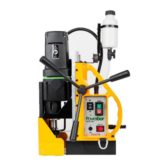
POWERBOR - PB70FRV
Magnetic drilling machine
Model Number
18P110, 18P230
This machine is CE approved.
Burgess Road
Sheffield, South Yorkshire
United Kingdom
S9 3WD
Tel: +44 (0) 114 2212 510
Fax: +44 (0) 114 2212 563
Email: info@Powerbor.co.uk
Website:
www.Powerbor.co.uk
1
Advertisement
Table of Contents

Related Manuals for POWERBOR PB70FRV


Summary of Contents for POWERBOR PB70FRV
- Page 1 PB70FRV Original instructions June 2019 POWERBOR - PB70FRV Magnetic drilling machine Model Number 18P110, 18P230 This machine is CE approved. Burgess Road Sheffield, South Yorkshire United Kingdom S9 3WD Tel: +44 (0) 114 2212 510 Fax: +44 (0) 114 2212 563 Email: info@Powerbor.co.uk...
-
Page 2: Table Of Contents
PB70FRV Original instructions June 2019 CONTENTS OF THE MANUAL Page Intended use General safety rules Information plate symbols Specification Operational safety procedures Operating instructions Extension cable selection Mounting of cutter Tapping Remedies for hole making problems Wiring diagram Machine Layout... -
Page 3: Intended Use
PB70FRV Original instructions June 2019 1) INTENDED USE The intended use of this magnetic drill is to drill holes in ferrous metals. The magnet is used to hold the drill in place whilst the drill is functioning. It is designed for use in fabrication, construction, railways, petrochemical and any other applications when drilling ferrous metal. -
Page 4: Information Plate Symbols
Remove from the mains prior to any maintenance. • Follow instructions for lubricating and changing accessories. • Inspect tool cords periodically and if damaged have them repaired by an authorized Powerbor service facility. • Inspect extension cords periodically and replace if damaged. •... -
Page 5: Specification
PB70FRV Original instructions June 2019 4) SPECIFICATION Maximum hole cutting capacity in .2/.3C steel = 70mm dia. x 50mm deep Arbor bore = 19.05mm (3/4") dia. Motor Unit Voltages 110V 50-60Hz 230V 50-60Hz Normal full load 17.8 A 1800 W 8.7 A... -
Page 6: Operational Safety Procedures
• When not in use ALWAYS store the machine in a safe and secure location. • ALWAYS ensure that approved POWERBOR™ agents conduct repairs. 6) OPERATING INSTRUCTIONS • Keep the inside of the cutter clear of swarf. It restricts the operating depth of the cutter. -
Page 7: Extension Cable Selection
PB70FRV Original instructions June 2019 7) EXTENSION CABLE SELECTION The machines are factory fitted with a 2 metre length of cable having three conductors 1.5mm² LIVE, NEUTRAL and EARTH. If it becomes necessary to fit an extension cable from the power source, care must be taken in using a cable of adequate capacity. -
Page 8: Remedies For Hole Making Problems
PB70FRV Original instructions June 2019 When using a 2 - IN - 1 Drill Tap, this type of tap is restricted to plate thicknesses of the diameter of the tapping size. ie: M24 = 24mm plate. This is due to the length of the plain portion of the shank after the threaded portion. - Page 9 PB70FRV Original instructions June 2019 Cutter not attached tightly to arbor. Retighten. Insufficient use of cutting oil or unsuitable type of Inject oil of light viscosity into the coolant-inducing oil. ring and check that oil is being metered into cutter when pilot is depressed.
-
Page 10: Wiring Diagram
PB70FRV Original instructions June 2019 11) WIRING DIAGRAM... -
Page 11: Machine Layout
PB70FRV Original instructions June 2019 12) MACHINE LAYOUT... -
Page 12: Exploded View Of The Machine
PB70FRV Original instructions June 2019 13) EXPLODED VIEW OF MACHINE... - Page 13 PB70FRV Original instructions June 2019 Part Description RD23603 COOLANT BOTTLE ASSEMBLY RD4269 M6×25 SOCKET CAP HEAD SCREW RD4414 SCREW M4 X 10 RD33338 FIXED RATCHET WHEEL W18XC209 SCREW 18Y3008 COOLANT BRACKET W18XC612 RETAINING BRACKET W18XC723 GLAND AL16/M16/A 18Y177 CONDUIT ASSEMBLY...
- Page 14 PB70FRV Original instructions June 2019 W18XC221 M5 X 16 CAPHEAD SCREW W18XC524 PINION END CAP W18XC252 M3 X 12 SCREW W18XC238 M4 BRASS NUT W18XC240 M4 X 20 MC SCREW W18Y181 LEAD & PLUG ASSEMBLY 110V W18XC503 MAINS CABLE UK PLUG 230V...
-
Page 15: Motor Breakdown
PB70FRV Original instructions June 2019 14) MOTOR BREAK DOWN It e m N o . P a rt N um be r D e s c ript io n It e m N o . P a rt N um be r D e s c ript io n Item No. -
Page 16: Control Panel And Parts List
PB70FRV Original instructions June 2019 15)CONTROL PANEL AND PARTS LIST W18XC456 MAGNET SWITCH W18XC511 FUSE HOLDER W18XC656 MOTOR SWITCH 110V W18XC657 MOTOR SWITCH 230V W18XC512 FUSE W18XC568 M5 X 20 C/SNK SCREW W18XC650 FWD/REV SWITCH W18XC252 M3 X 12 SCREW... -
Page 17: Maintenance
Original instructions June 2019 16) MAINTENANCE In order to ‘get the best life’ out of your Powerbor machine always keep it in good working order. A number of items must always be checked on Powerbor machines. Always before starting any job make sure the machine is in good working order and that there are no damaged or loose parts. -
Page 18: Trouble Shooting
PB70FRV Original instructions June 2019 17) TROUBLE SHOOTING Magnet and motor do not function - The magnet switch is not connected to the power supply - Damaged or defective wiring - Defective magnet switch - Defective control unit - Defective power supply... -
Page 19: Cutter Selection
PB70FRV Original instructions June 2019 18) CUTTER SELECTION Material Material Hardness Cutter Mild and free cutting steels <700N/mm² Mild and free cutting steels <850N/mm² Steel angle and joists <700N/mm² Steel angle and joists <850N/mm² Plate and sheet steel <700N/mm² Plate and sheet steel <850N/mm²... -
Page 20: Warranty + Ce Statement
Powerbor™ or its designated distributor within a period of (30) days from the purchase date. Failure to do so will void the warranty. If the stated is adhered to Powerbor™ will repair or replace (at its option) without charge any faulty items returned. - Page 21 Original instructions June 2019 CE Declaration of Conformity On our sole responsibility we declare that this product, the Powerbor PB70 FRV Drill, is in conformity with the following standards and standard documents :- EN61029-1:2009 - Safety of Transportable Motor Operated Electric Tools EN61000-6-2:2005 - Electromagnetic Compatibility (EMC).
Need help?
Do you have a question about the PB70FRV and is the answer not in the manual?
Questions and answers