Table of Contents
Advertisement
Quick Links
POWERBOR - PB70 DRILL
WARNING !
When using electric power tools basic safety
precautions should always be used to
reduce the risk of fire, electric shock and
personal injury.
Read all of these instructions before
attempting to operate this product and save
these instructions
The POWERBOR range of machines are exclusively manufactured by
G&J Hall Ltd, Burgess Road, Sheffield, S9 3WD, England
ORIGINAL INSTRUCTIONS
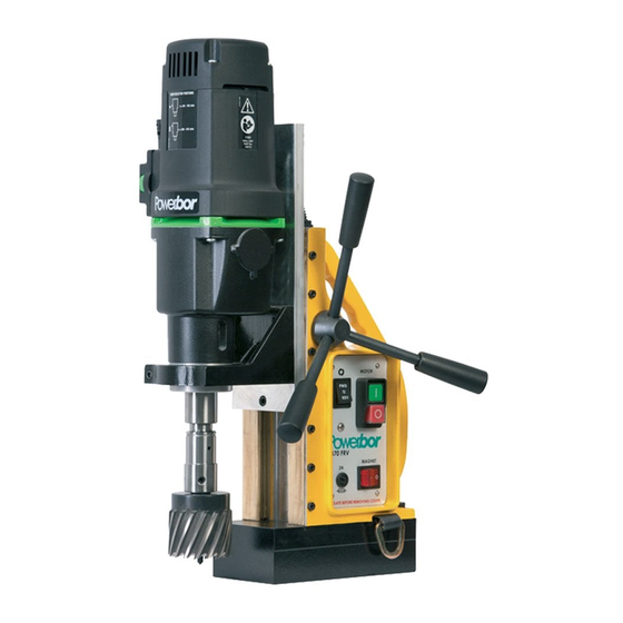
Machine shown
PB70 - without the
safety guard for clarity.
PB70 - W18XC1052 - Revised 040113
Advertisement
Table of Contents

Related Manuals for POWERBOR PB70


Summary of Contents for POWERBOR PB70
- Page 1 Machine shown PB70 - without the safety guard for clarity. The POWERBOR range of machines are exclusively manufactured by G&J Hall Ltd, Burgess Road, Sheffield, S9 3WD, England PB70 - W18XC1052 - Revised 040113...
-
Page 2: Table Of Contents
Motor Protection Coolant 7 - Lifting handles/transportation. Maintenance and servicing 1 - Regular cleaning, maintenance and lubrication. 2 - Servicing by manufacturer. 3 - Special Tools 4 - Blockages of chips or work piece fragments. PB70 - W18XC1052 - Revised 040113... -
Page 3: Machine Specification
These factors may increase the vibration experienced by the operator, each individual application of the tool should be assessed for the effect of these application variable factors, before exposure. PB70 - W18XC1052 - Revised 040113... -
Page 4: Explanation Of Symbols Used
Read and understand the instruction manual - before operating this tool. Caution ! / Attention ! Instruction Manual WEEE - Waste of Electrical and Electronic Equipment This tool should be disposed of as Electrical & Electronic Waste. PB70 - W18XC1052 - Revised 040113... -
Page 5: Prohibited Use Of Power Tool
The power tool should be used in a weather protected environment and be used with the accessories provided or Powerbor recommended accessories only. The power tool can be used vertically, horizontally and upside down, provided the magnetic adhesion and work environment allow. - Page 6 Always wear ear protection. Always wear head protection. Always wear non-skid safety shoes. Where appropriate wear a dust mask and gloves depending on the working environment. WORK IN A SAFE MANNER AT ALL TIMES PB70 - W18XC1052 - Revised 040113...
-
Page 7: Special Safety Precautions - Magnetic Drills
Care should be taken with the ejected slug, this will be both hot and sharp, gloves should be worn when handling the slug. PB70 - W18XC1052 - Revised 040113... -
Page 8: Electrical Safety
This is both to protect the operator and to protect the motor inlet from ingress of harmful dust particles. Operators should wear suitable dust masks if dust is created whilst working. PB70 - W18XC1052 - Revised 040113... - Page 9 12 - Secure work Where possible use clamps or a vice to hold the work. It is safer than using your hand. 13 - Do not overreach Keep proper footing and balance at all times. PB70 - W18XC1052 - Revised 040113...
- Page 10 22 - Have your tool repaired by a qualified person This electric tool complies with the relevant safety rules. Repairs should only be carried out by qualified persons using original spare parts, otherwise this may result in considerable danger to the user. PB70 - W18XC1052 - Revised 040113...
-
Page 11: Unpacking And Assembly
UNPACKING AND ASSEMBLY The Powerbor PB70 comes in a rugged blow moulded carrying case Before first use:- Remove the machine from the carrying case. (Note:- 22kg weight) Fit the three screw in handles to the pinion shaft. Fit the safety guard as shown in the instructions, see “Using the safety guard”... -
Page 12: Illustrated Description Of Functions
MOTOR SPEED ADJUST DRILL UNIT/MOTOR MOTOR TORQUE BOOST GEAR SELECTOR MOTOR ON/OFF SWITCH MAGNET ON/OFF SWITCH SPINDLE FWD/REV SWITCH SAFETY GUARD 2A FUSE (MAGNET) ‘D’ LOOPS FOR SAFETY STRAP ARBOR ELECTRO - MAGNET BASE PB70 - W18XC1052 - Revised 040113... -
Page 13: Limitations On Ambient Conditions
° Ambient temperatures of >45 C should be avoided. STANDARD ACCESSORIES The PB70 is supplied in a rugged carrying case with the following as standard :- MT3 to 3/4” Weldon shank arbor (50mm cut depth) Safety ratchet strap Safety guard 250ml bottle &... -
Page 14: Setting And Testing
First ensure the ejector pin is in place. Align the flats with the two fixing screws. Push the cutter up into the arbor until it stops. Tighten the two fixing screws onto the cutter flats with the hex keys supplied. PB70 - W18XC1052 - Revised 040113... -
Page 15: Removing The Mt3 Arbor
With the Weldon shank arbor removed, the electro-magnetic drill stand can be used with twist drills or any other suitable cutting tool or holder with a standard MT3 shank. The PB70 has a twist drill Ø capacity of 32mm. For smaller twist drills a 5/8” 3 jaw chuck mounted on an MT3 shank can be used. -
Page 16: Guards
The security of the magnet should always be physically checked BEFORE starting the drill unit. The magnet is protected by a 20mm 2A fast acting fuse (G). PB70 - W18XC1052 - Revised 040113... -
Page 17: Workpiece Material And Size Limitations
CUTTING SPEEDS/MATERIALS—HSS CUTTERS The PB70 is a 2 gear variable speed drill unit with nominal load speeds of 60 - 140 and 200 - 470 rev/min. Under load the PB70 will maintain its speed depending on the load applied. It has a torque boost function to adjust the torque gain between 1.4 - 2.8 rated. - Page 18 OPERATION - SPINDLE SPEED - GEAR SELECTOR The speed of the motor on the PB70 can be controlled by As viewed from changing the gear ratio selector (J) to position I or II.
- Page 19 OPERATION - SPINDLE - SPEED CONTROL The PB70 has variable speed control with load feedback, this means the drill will attempt to maintain the set speed when under load, by compensating electronically. Speed is adjusted by rotating the speed control knob (K).
-
Page 20: Tapping
TAPPING The PB70, in addition to drilling with annular cutters, is designed to allow the tapping of screw threads. The tapping capacity of the PB70 is M6 to M24. This machine has variable speed and both forward and reverse spindle rotation. -
Page 21: Tapping
TAPPING SPEEDS rev/min Tap Size Mild Steel Alloy Steel The tapping speeds shown above are for guidance only, condition of the cutter and specific material conditions will dictate actual speeds required. PB70 - W18XC1052 - Revised 040113... -
Page 22: Reversing Of The Handles
The pinion shaft can be reversed on this type of machine to allow the drill better access in confined spaces. When the handles are reversed, again the operator should still have full access to the control panel before using the machine. PB70 - W18XC1052 - Revised 040113... -
Page 23: Using The Drill With Annular Cutters
This will be both hot and sharp. Care should be taken when handling the slug. Care should be taken that the ejection slug is safe and can not injure anyone in the vicinity, the slug should be prevented from falling where possible. PB70 - W18XC1052 - Revised 040113... -
Page 24: Motor Protection
MOTOR PROTECTION The PB70 has both a mechanical clutch and electronic overload protection to protect the motor from overload situations. If the mechanical clutch operates, the spindle will stop and a rapid clicking sound from the motor and gearbox will be heard, reduce the feed rate or withdraw the cutter to resume. - Page 25 5/8” (16mm) diameter. of the machine. not need to be magnetic. PB70 - W18XC1052 - Revised 040113...
- Page 26 P O W E R B O R W A R R A N T Y S T A T E M E N T Powerbor warrants its magnetic drills for one (1) year from the date of purchase against defects due to faulty material or workmanship and will repair or replace (at its option) without charge, any items returned.
- Page 27 PB70 WIRING DIAGRAMS PB70 - W18XC1052 - Revised 040113...
- Page 28 PB70 CONTROL PANEL COMPLETE —230V 17&18 18Y175 HANDLE & KNOB 18X520 KNOB SHADED PARTS IN THE TABLE ABOVE ARE 18X430 CABLE STRAIN RELIEF GLAND SHOWN ON THE CONTROL PANEL EXPLODED 18X723 M16 GLAND VIEW. 18Y177 CONDUIT ASSEMBLY PB70 - W18XC1052 - Revised 040113...
- Page 29 PB70 CONTROL PANEL PARTS DIAGRAM PB70 - W18XC1052 - Revised 040113...
- Page 30 SAFETY RING - EIB 80201324 18ZD38 PIN - EIB 80200280 18ZD39 GEAR BOX HOUSING - EIB 71521400 18ZD71 EXT CIRCLIP 20x1.2 18ZD40 DEEP GROOVE BEARING 6000 GEARBOX COVER - EIB 7152B625 18ZD72 18ZD41 NEEDLE BEARING RNA 4900 PB70 - W18XC1052 - Revised 040113...
- Page 31 18X628 MT3 ARBOR PISTON 18X206 19MM INTERNAL CIRCLIP 18X207 MT3 ARBOR WASHER 18X204 M10 x 10 CUP POINT SCREW PB70 SAFETY STRAPS Item Part No. Description 18X535 HOOK STRAP ASSEMBLY 18X533 RATCHET STRAP ASSEMBLY PB70 - W18XC1052 - Revised 040113...
-
Page 32: Ce Declaration Of Conformity
CE Declaration of Conformity On our sole responsibility we declare that this product, the Powerbor PB70 Drill, is in conformity with the following standards and standard documents :- EN61029-1:2009 - Safety of Transportable Motor Operated Electric Tools EN61000-6-2:2005 - Electromagnetic Compatibility (EMC). Generic standards.
Need help?
Do you have a question about the PB70 and is the answer not in the manual?
Questions and answers