
Subscribe to Our Youtube Channel
Related Manuals for Ancona UCR630


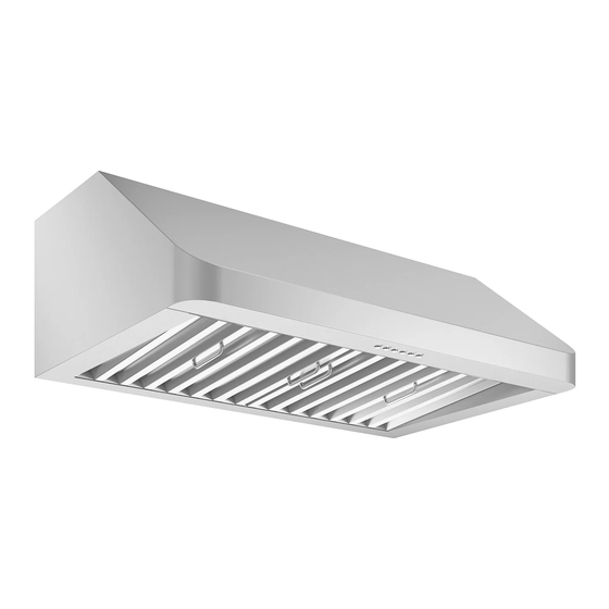
Summary of Contents for Ancona UCR630
- Page 1 UCR630 - UCR636 IMPORTANT SAFETY INSTRUCTIONS Carefully read the following important information regarding installation safety and maintenance. Keep these instructions for future reference. 29/05/2018 MAAN1284-04...
- Page 2 • The installation in this manual is intended for qualified installers, service technicians or persons with similar qualified background. Installation and electrical wiring must be done by qualified professionals and in accordance with all applicable codes and standards, including fire-rated construction. •...
- Page 3 • Clean ventilating fan frequently. • Always use appropriate cookware and utensils size. • Always use cookware appropriate for the size of the surface element. To reduce the risk of injury to persons in the event of a stove top grease fire: •...
-
Page 4: Tools Needed
Tools Needed : Measuring Marker or tape Utility knife pencil Level Flat-blade Powered and Phillips screwdriver screwdrivers or drill Page 3... -
Page 5: Parts Supplied
Parts Supplied : Under Cabinet Range Hood ange Hood 2 Baffle filter spacers 4 Baffle filter handle 2 Baffle filters andle scre s Hood-mounting Bracket cre Hood-mounting Bracket rea e unne Page 4... - Page 6 • Vent system must terminate to the outside (roof or side wall). • DO NOT terminate the vent system in an attic or other enclosed area. • DO NOT use 4” (10.2 cm) laundry-type wall caps. Cabinet • Use metal/aluminum vent only. Rigid metal/ Cabinet aluminum vent is recommended.
-
Page 7: Calculating Vent System Length
IMPORTANT: A minimum of 7” round (standard for this range hood) or 3-1/4 x 10” rectangular duct (purchased separately) must be used to maintain maximum air ow ef cien efficiency. Always use rigid type metal/aluminum ducts if available to maximize air ow when connecting to provided duct. -
Page 8: Venting Methods
Venting Methods : This range hood is factory set for venting through the roof or wall. Vent work can terminate either through the roof or wall. To vent through a wall, a 90° elbow is needed. IMPORTANT: NEVER exhaust air or terminate duct work into spaces between walls, crawl spaces, ceiling, attics or garages. -
Page 9: Electrical Requirements
Electrical Requirements : IMPORTANT: Observe all governing codes and ordinances. It is the customer’s responsibility: To contact a quali ed electrical installer. If codes permit and a separate ground wire is used, it is recommended that a quali ed electrician determine that the ground path is adequate. - Page 10 Preparation : Advanced Preparations: Be familiar with the controls of the range hood by reading through Range Hood Operations, Page 12. Place the range hood on a at, stable surface. Connect the range hood to a designated standard outlet (120-Volt, 60Hz, AC only) and turn on the range hood.
- Page 11 Installations (refer to Page 4 for parts): eas re the distance bet een st e t p and the b tt f ran e h d distance f 24 t is rec ended ith a ini f r as st e t ps 1.
- Page 12 Installation (Continued) : 5. Store excess wires in the wiring box. 6. Drop oil tunnel into recess support near rear of hood. Refer to Figure 8. 7. To install baf e lters and stainless spacer(s), refer to Baf e Filters and Stainless Steel Spacers on Page 18 for baf e lter and stainless spacer placement.
-
Page 13: Range Hood Operations
Range Hood Operations : Control Panel Layout and Buttons Con gurations: his ran e h d is e ipped ith six electr nic c ntr ls ersi ed p erf l centrif al s irrel ca e t r ith stainless steel rease t nnel stainless steel baf e plters and spacers t bri ht li hts and 2... - Page 14 Range Hood Operations (Continued) : Control Panel Layout and Buttons Con gurations: During this 3-minutes delay, changing speeds will not affect the countdown. Immediate Power-off While the fans are in 3-minute power-off delay mode, press the Power Control (On/Off) button once to turn OFF the fans immediately.
-
Page 15: Troubleshooting
Troubleshooting : 1. f the ran e h d r li ht d es n t perate hec if the ran e h d has been pl ed in after installation: sure that all power has been turned back ON, fused not blown and all electrical wiring are properly con- nected. -
Page 16: Specifications
Use and Care Information : Operations: Read and understand all instructions and warnings in this manual before operating the appliance. Save these instructions for future reference. Always leave safety grills and lters in place. Without these components, operating blowers could catch on to hair, ngers and loose clothing. - Page 17 WARNING Measurements and Diagrams : This range hood is 10" high (254 mm) - For electric cook top you need min. 34" (863 mm) clearance distance between bottom of cupboard and cook top; - For gaz cook top you need 40" (1015 mm) clearance. All measurements in parenthesis are in millimeters.
- Page 18 All measurements in parenthesis are in millimeters. All inch measurements are converted from millimeters, thus inch measurements are estimated. Rear Knockout Holes: Hood-Mounting Bracket: Page 17...
- Page 19 Baffle Filters and Stainless Steel Spacers: 30” Range Hood 36” Range Hood Circuit Diagram: Page 18...
- Page 20 Description Description Screws (3/16” x 3/8”) Stainless Steel Spacer (Size Varies) Hood Casing Baffle Filter Hood Mounting Bracket (Optional) Baffle Handle Screws (3/16” x 3/8”) (Optional) Electrical Assembly Stainless Steel Grease/Oil Tunnel Screws (3/16” x 3/8”) Blower Assembly Wiring Box Light Panel Screws (3/16”...
- Page 21 Description Description Air Chamber Right Squirrel Cage Screw Cap Gasket Left Squirrel Cage Screws (3/16” x 3/8”) Left Locknut Left Motor Air Flow Grill Right Motor Screws (3/16” x 3/8”) Safety Screen Right Locknut Page 20...
- Page 22 Description Description Electrical Box Screws (3/16” x 3/8”) Screws (3/16” x 3/8”) Transformer Processor Board Screws (3/16” x 3/8”) Electrical Box Cover Capacitor Setup Board Screws (3/16” x 3/8”) Gasket Page 21...
- Page 23 Replacing Filters: eplace filters if the t d e t a e and pr l n ed se Replacing the light bulb:...
Need help?
Do you have a question about the UCR630 and is the answer not in the manual?
Questions and answers