
Related Manuals for EVGA SR-3 DARK


Summary of Contents for EVGA SR-3 DARK
- Page 1 EVGA SR-3 DARK (160-CX-W999) User Guide EVGA SR-3 DARK Specs and Initial Installation - 1 -...
-
Page 2: Table Of Contents
Motherboard Specifications ....................- 6 - Unpacking and Parts Descriptions ..................- 8 - EVGA SR-3 DARK Motherboard LED reference ............. - 10 - EVGA SR-3 DARK Motherboard Component Legend ............. - 16 - PCIe Slot Breakdown ......................- 28 - M.2 / U.2 Slot Breakdown .................... - Page 3 Multifunction LED Indicator .................... - 149 - POST Beep codes ......................- 151 - POST Port Debug LED ....................- 152 - POST Codes ......................- 153 - EVGA Glossary of Terms ....................- 158 - Compliance Information ..................- 161 - - 3 -...
-
Page 4: Evga Sr-3 Dark
I/O options. If you’ve been holding out for a serious motherboard to upgrade, the time is at hand. Lastly, a motherboard is only as good as its BIOS, and the EVGA SR-3 DARK features EVGA’s newest UEFI/BIOS GUI with a focus on overclocking and functionality in a lean, straightforward package. -
Page 5: Parts Not In The Kit
A 6mm Allen Key (not included) is required to remove the stop fittings. EVGA assumes you have purchased all the necessary parts needed to allow for proper system functionality. For a full list of supported CPUs on this motherboard, please visit www.evga.com/support/motherboard... -
Page 6: Motherboard Specifications
EVGA SR-3 DARK (160-CX-W999) Motherboard Specifications Size: ❑ EATX form-factor of 11.99 inches x 12.99 inches (305x330mm) Socket LGA 3647 Narrow 30u Microprocessor support: ❑ Intel Socket 3647 XEON W-3175X/Cascade Lake-SP Processors ® ® Operating Systems: ❑ Supports Windows 10 64bit System Memory support: ❑... - Page 7 EVGA SR-3 DARK (160-CX-W999) Onboard Audio: ❑ Creative Core3D Quad-Core Audio Processor (CA0132) Supports 5.1 Channel audio with Optical S/PDIF Out Onboard LAN: ❑ 2x Intel X557-AT2 10GbE (1000/10000) Ethernet PHY ® 1x Intel i219LM Gigabit (10/100/1000) Ethernet PHY ®...
-
Page 8: Unpacking And Parts Descriptions
EVGA SR-3 DARK (160-CX-W999) Unpacking and Parts Descriptions The following accessories are included with the EVGA SR-3 DARK Motherboard: - 8 -... - Page 9 EVGA SR-3 DARK (160-CX-W999) - 9 -...
-
Page 10: Evga Sr-3 Dark Motherboard Led Reference
EVGA SR-3 DARK (160-CX-W999) EVGA SR-3 DARK Motherboard LED reference The EVGA SR-3 DARK Motherboard has several LEDs indicating power, connectivity, and activity. Below is the location of the LEDs and their function. - 10 -... - Page 11 EVGA SR-3 DARK (160-CX-W999) LED Legend DIMM3 Fail PE4 OK Memory Channel 1,2,3 Power DIMM3 Active PE5 Enable VCCIN Power DIMM2 Fail PE5 OK Memory Channel 4,5,6 Power DIMM2 Active PE6 Enable CPU FIVR Power Error DIMM1 Fail PE6 OK...
- Page 12 EVGA SR-3 DARK (160-CX-W999) 8. Memory DIMM 4 Fail a. RED: DIMM/Memory has failed POST 9. Memory DIMM 5 Status a. WHITE: DIMM detected and present 10. Memory DIMM 5 Fail a. RED: DIMM/Memory has failed POST 11. Memory DIMM 6 Status a.
- Page 13 EVGA SR-3 DARK (160-CX-W999) 22. PCIe Enabled for PE5. The LED will remain off when this PCIe slot is disabled or unpopulated. a. GREEN: PE5 slot can be used with installed CPU. 23. PCIe Status for PE6. The LED will remain off when this PCIe slot is disabled or unpopulated.
- Page 14 EVGA SR-3 DARK (160-CX-W999) 35. +12V_CPU Power [Hidden by waterblock] a. WHITE: Voltage present (Does not mean PSU is outputting in-spec, only that this specific voltage is detected) 36. VCCIO Power [Hidden by waterblock] a. WHITE: Voltage present (Does not mean PSU is outputting in-spec, only that this specific voltage is detected) 37.
- Page 15 EVGA SR-3 DARK (160-CX-W999) 47. Multifunction POST Indicator a. During boot it will cycle many different hexadecimal post codes with a range of 00-FF and this indicates what aspect of the Power On Self Test (POST) is currently running. i. For a list of POST Codes, please see Page 153.
-
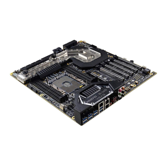
Page 16: Evga Sr-3 Dark Motherboard Component Legend
EVGA SR-3 DARK (160-CX-W999) EVGA SR-3 DARK Motherboard Component Legend The EVGA SR-3 DARK Motherboard with the Intel C622 and PCH Chipset. ® Figure 1 shows the motherboard and Figure 2 shows the back panel connectors FIGURE 1. SR-3 DARK Motherboard Layout... - Page 17 EVGA SR-3 DARK (160-CX-W999) Component Legend CPU Socket LGA3647 M.2 Socket 3 Key-M 110mm (PM2) BIOS Selector Switch Intel C622 PCH (Southbridge) PCIe Slot x16/x8 CMOS Battery PWM Fan Headers (2 amp) PCIe Slot x8 PCIe Disable Switches PWM/DC Fan Headers (2 amp)
- Page 18 EVGA SR-3 DARK (160-CX-W999) Figure 2. Chassis Rear Panel Connectors Analog Audio Port Breakdown 2/2.1 Channel 4.0/4.1 Channel 5.1 Channel Dark Green Head Phone Head Phone Head Phone Front Speaker / Front Speaker/ Front Speaker/ Light Green Speaker+Sub Out Speaker+Sub Out Speaker+Sub Out...
- Page 19 EVGA SR-3 DARK (160-CX-W999) Component Legend Descriptions 1. CPU Socket 3647 This is the interface for the Central Processing Unit (CPU), and supports Intel ® Xeon models compatible with the Intel LGA3647 Socket, based on Intel ® Xeon W-3175X and Cascade Lake-SP architecture.
- Page 20 Alternatively, if no power cable is connected or detected, the system will not POST and will hang at POST code “00.” *Note – EVGA recommends at least 2 (two) 8-pin EPS connectors be plugged in to the motherboard. Although one 8-pin EPS connector may be sufficient to boot, less powerful processors and low-load scenarios may still cause the board to shut off due to insufficient power.
- Page 21 EVGA SR-3 DARK (160-CX-W999) supports NCQ, TRIM, hot swap capability (provided the proper HDD/SSD bays/racks are installed), and RAID levels 0/1/5/10. 10. Intel sSATA Mini-SAS 6Gbit/s Port ® The Intel C622 PCH also supports an additional 4-ports of SATA 3/6 Gbit/s ®...
- Page 22 EVGA SR-3 DARK (160-CX-W999) This socket will support Key-M devices of 110mm, 80mm, 60mm, and 42mm length. This connector can utilize only PCIe/NVMe-based M.2 SSDs. 14. PCIe Slot x16/x8* PCIe x16/x8 slots are primarily used for video cards. These full-length slots will provide 8 or 16 lanes of bandwidth to a full-size card, and are backwards- compatible with x8, x4, and x1-length cards.
- Page 23 EVGA SR-3 DARK (160-CX-W999) clear CMOS button will normally allow you and your system back into the default BIOS. 19. Debug POST Indicator / Hardware Monitor This is a four-digit POST code reader, which displays in sets of 7-digit LED.
- Page 24 USB2 and will use the standard “HD Audio” jack. Some systems may have two headers: one labeled HD Audio, and one labeled AC’97 – an AC’97 cable is not compatible with this header on the SR-3 DARK. 23. Front Panel Connectors The Front panel connectors are the four main chassis connections.
- Page 25 This allows you to swap between three physically different BIOS chips. This also makes it substantially easier to hotflash a BIOS if needed. If instructions are needed for hotflashing a BIOS, please contact EVGA Customer Service (Page 148 for contact info).
- Page 26 EVGA SR-3 DARK (160-CX-W999) a successful POST, various tones for USB initialization, and other beeps to indicate an issue during the post process. Please see Page 151 for more details. 30. BIOS SafeBoot Button Pressing this button while the system is running will reboot the motherboard directly into the BIOS without clearing CMOS.
- Page 27 EVGA SR-3 DARK (160-CX-W999) Card Slots The SR-3 DARK features six x16 PCIe slots and two Socket 3 Key-M M.2 110mm slots (PM1/PM2) (backwards compatible with Key-M 80mm, 60mm, and 42mm). - 27 -...
-
Page 28: Pcie Slot Breakdown
EVGA SR-3 DARK (160-CX-W999) PCIe Slot Breakdown ® PCIe Lane Distribution (Socket 3647 Intel Xeon W-3175X processors have 48 lanes, while Cascade Lake-SP processors have 64 lanes.) PE1 – x16 (Gen3, x16 lanes from CPU, x8 shared with PE3) ❑... -
Page 29: M.2 / U.2 Slot Breakdown
EVGA SR-3 DARK (160-CX-W999) M.2 / U.2 Slot Breakdown M.2 Lane Distribution M.2 Key-M (110mm, Left side of board, PM1) – x4 from CPU ❑ o M.2 Enable/Disable is set within the BIOS o This M.2 Key-M slot shares lanes with PE5. Installing an M.2 device in PM1 will also enable PM2 and disable PCIe slot PE5. -
Page 30: Preparing The Motherboard
Installing the CPU and Cooling Device Note: EVGA strongly recommends that you completely disconnect AC power from your power supply prior to changing your CPU. This ensures the motherboard will use the correct startup procedure for all onboard devices. If AC power is not disconnected, the replacement is still supported, but may require additional reboots to boot successfully. - Page 31 EVGA SR-3 DARK (160-CX-W999) 1. Place the CPU and clip upside-down on a clean, flat surface. Line up the corresponding arrows on the CPU clip to the CPU, and lower the CPU onto the clip until it latches into place.
-
Page 32: Installing The Cpu Cooling Device
EVGA SR-3 DARK (160-CX-W999) 4. Carefully pick up the CPU cooler. Align the notches on the CPU to the notches in the socket, and also align the mounting dowels to the holes in the clip. When ready, lower the processor and cooler straight down into the socket. -
Page 33: Installing System Memory
® and Cascade Lake-SP. It is recommended to always use a 6 DIMM Hexa- Channel kit for the SR-3 DARK. Fill the memory slots in the following order: 3, 6, 2, 5, 1, and 4. See chart below: Use the following procedure to install memory DIMMs. Note that there is a key notch near the center of the DIMM slots. -
Page 34: Installing The I/O Shield
EVGA SR-3 DARK (160-CX-W999) ® Note: The memory controller on Xeon W-3175X and Cascade Lake-SP CPUs run at a default frequency of 2933MHz. Achieving memory speeds above 2933MHz may require using the XMP profile or manual setting of the memory timings, frequency and voltages. -
Page 35: Securing The Motherboard Into A System Case
6. See the picture below for a zoomed-in view of a hole to place over a standoff, as well as the locations of standoff holes for the SR-3 DARK. - 35 -... - Page 36 EVGA SR-3 DARK (160-CX-W999) 1. All safe locations to secure the board to a standoff are circled in blue. 2. Keep in mind that when the screws are installed, but not fully tightened, the motherboard should have 1-2mm of movement; this can help when mounting cards or tight-fits with other components.
-
Page 37: Installing M.2 Devices
3 (for SSDs) – are installed differently. Below are images from an installation of an SSD on one of the Socket 3 Key-M 110mm slot of the SR-3 DARK. 1. Before you can install an M.2 device, you must first remove the screw that comes pre-attached to the Socket 3’s retention standoff;... - Page 38 EVGA SR-3 DARK (160-CX-W999) 3. Insert the M.2 device at a slight angle of approximately 45 degrees to the board. This will allow the contacts (colloquially called “Gold Fingers”) to seat completely into the slot. If the device is fully seated,...
-
Page 39: Tested Cpu And Memory
EVGA SR-3 DARK (160-CX-W999) For further M.2 setup instructions, please see Page 55. Tested CPU and Memory Core Count Frequency PCI-E Lanes Skylake-X XEON® W-3175X 28 Cores + HT 3.1 GHz Skylake-SP XEON® 8180 28 Cores + HT 2.5 GHz Cascade Lake-SP XEON®... - Page 40 EVGA SR-3 DARK (160-CX-W999) Memory G.SKILL F4-2133C15Q-16GRR G.SKILL F4-2133C15Q-32GRR Crucial CT4G4DFS8213.8FA1 CORSAIR CMK32GX4M4A2133C13 CORSAIR CMK16GX4M4A2133C13 CORSAIR CMK64GX4M8A2133C13 G.SKILL F4-2133C15D-8GRR Kingston HX421C14FBK4/16 CORSAIR CMK32GX4M2A2400C14 G.SKILL F4-2400C15Q-16GRR CORSAIR CMK16GX4M4A2400C14 CORSAIR CMD32GX4M4A2400C14 G.SKILL F4-2400C15Q-64GRK G.SKILL F4-2400C14Q-16GRK mushkin Blackline 997199F G.SKILL F4-2400C15D-8GRR G.SKILL F4-2666C15Q-16GRR...
-
Page 41: Tested M.2 Key-M
EVGA SR-3 DARK (160-CX-W999) Tested M.2 Key-M PCIE INTERFACE ADATA ASX800NP-256GM-C 256G M.2 PCIE Samsung MZ-V7E250 970 EVO Samsung MZ-V7P512 970 PRO Samsung MZ-VKV512 950 PRO Samsung MZ-V6P512 960 PRO Samsung MZ-VPV2560 256G SM951 NVME Samsung MZ-HPU128T/004 128G XP941 Samsung MZ-HPV1280 128G SM951... - Page 42 EVGA SR-3 DARK (160-CX-W999) Tested U.2 - 42 -...
-
Page 43: Connecting Cables
Connecting Cables Note: the following images do not necessarily represent the physical orientation of their respective headers on the EVGA SR-3 DARK. Rather, these graphical representations are designed to provide a basic physical footprint and the cable pinouts for each component. - Page 44 Firmly plug the power supply cable into the connector and make sure it is secure. The 24-pin Power Connector may be standard or right-angled depending on your motherboard model. The SR-3 DARK motherboard uses a right-angle 24pin ATX connector. 6-pin PCIe...
- Page 45 CPU power. IMPORTANT: The SR-3 DARK features four (4) 8pin EPS connectors. EVGA strongly recommends to connect at least two (2) EPS connectors to provide sufficient power to your CPU and motherboard, even for light or low-load applications.
- Page 46 EVGA SR-3 DARK (160-CX-W999) Front Panel Header The front panel header on this motherboard is used to connect the following four cables: PWRLED ❑ Attach the front panel power LED cable to these two pins of the connector. The Power LED indicates the system’s status. When the system is powered on, the LED will be on.
- Page 47 EVGA SR-3 DARK (160-CX-W999) Fan Header This motherboard line only features 4-pin fan headers, which are backwards compatible with 3-pin fan connectors. The CPU1 and CPU2 fan headers control fans via PWM. The remaining headers control fans by either PWM or DC controls.
- Page 48 EVGA SR-3 DARK (160-CX-W999) USB Headers This motherboard contains USB 3.1 and 3.0 ports that are exposed on the rear panel of the chassis. The motherboard contains 1x 19-pin internal header connectors onboard that can be used to connect an optional external bracket or device containing up to two (2) USB 3.1 Gen1 ports.
- Page 49 (2) USB 2.0 ports. The SR-3 DARK also features an onboard USB 2.0 port header, near the CPU Fan headers. This header has a specific purpose – to allow you to flash the BIOS without an installed CPU using the included USB flash drive.
- Page 50 EVGA SR-3 DARK (160-CX-W999) Front Panel Audio Header Front panel audio supports HD Audio for stereo/gaming headphones or 2.1 speakers, and a Mic. NOTE: HD Audio headers are not compatible with AC’97 connectors, which may be used on older chassis. Connecting an AC’97 cable/connector to your motherboard may damage either or both the motherboard and the cable connected to it.
-
Page 51: Onboard Buttons
EVGA SR-3 DARK (160-CX-W999) Drive Headers (SATA/ U.2) SATA 3/6Gbit/s is the current standard for HDD/SSD/Optical interface. These cables are the data interconnect for the motherboard. Your HDD/SSD/Optical interface will still require a separate power connection from your power supply. - Page 52 EVGA SR-3 DARK (160-CX-W999) Clear CMOS Button The motherboard uses CMOS RAM to store set parameters. Clear the CMOS by pressing the Clear CMOS button on the motherboard PCB or on the external I/O Panel. External Clear CMOS Button RESET and POWER Button These onboard buttons allow you to easily turn on/off the system.
-
Page 53: First Boot
EVGA SR-3 DARK (160-CX-W999) First Boot BIOS Update When you power on the system for the first time (or after a BIOS update/reset) it may take a little longer than expected, and follow with a warning message on the screen reading “BIOS checksum error”. - Page 54 EVGA SR-3 DARK (160-CX-W999) prefer, but the XMP will generally get the memory running at the memory manufacturer’s specification with little to no effort. HDD/SSD/M.2/U.2 Setup Next, click “Boot” from the menu list at the top. “Boot Option #1” should show the device that you intend to install your operating system.
-
Page 55: Ssd, Pcie Ssd, And Nvme Ssd Installation Steps
EVGA SR-3 DARK (160-CX-W999) M.2 SSD, PCIe SSD, and NVMe SSD Installation steps M.2 is a very fast card bus that can use multiple connecter types to connect many types of devices, such as WiFi or SSDs, in a very small and power efficient package. M.2 devices can be connected via an M.2 card slot or through PCIe by using an M.2 to PCIe adapter. - Page 56 BIOS/UEFI and go to “Advanced – Onboard Device Configuration,” and confirm that the appropriate “M.2 Socket3” slot is enabled. The SR-3 DARK is designed to auto-detect M.2 devices and enable the M.2 slot automatically, but you should confirm that the setting is enabled if you have difficulty getting the device to appear in the BIOS or the OS.
- Page 57 EVGA SR-3 DARK (160-CX-W999) Internal SATA, sSATA, VROC RAID Controller This section introduces RAID, RAID levels, and the basics of the controller integrated into the PCH. It covers the basics of what RAID does, how RAID works, and why you may or may not want to use RAID.
- Page 58 EVGA SR-3 DARK (160-CX-W999) its quality, and many other factors; but the number should give you a ballpark estimate on what to expect as a final capacity once formatted. Please see below for examples of what to expect when you build an array of each type.
- Page 59 EVGA SR-3 DARK (160-CX-W999) Because RAID0 is only designed to distribute the data being written across multiple devices to improve performance there is **NO FAULT TOLERANCE**, meaning if one drive fails, the array fails. It MAY be possible to recover the data but that usually requires a data recovery service, which is not guaranteed and is usually very expensive.
- Page 60 EVGA SR-3 DARK (160-CX-W999) The array depictions below show how this issue scales to larger arrays. In fact, due to the lack of fault tolerance, the potential failure rate actually increases because of the addition of more drives that can physically fail.
- Page 61 EVGA SR-3 DARK (160-CX-W999) The Good- • RAID1 allows you to suffer a catastrophic failure of 1 drive with no ill effects to the data being stored. • Because data is stored on 2 drives at once, read speeds typically increase a little, but not to the speed of RAID5 and, certainly, not to the speed of RAID 0.
- Page 62 EVGA SR-3 DARK (160-CX-W999) use four 1TB drives to create your RAID5, you will only have the capacity of three 1TB drives; likewise, if you use five 1TB drives to create your array, you will only have the capacity of four 1TB drives. RAID5 requires a minimum of three drives, and the maximum is set by the RAID controller;...
- Page 63 EVGA SR-3 DARK (160-CX-W999) drive than there is data set. This method of data distribution shows that as long as you have three (3) copies of each data set (Data-A, Data-B, and DATA-C), the array will be functional and capable of rebuilding when you add in replacement drive in. And while this is not mathematically correct for HOW the data distribution works, it is a good visualization to understand the basics of how it works.
- Page 64 EVGA SR-3 DARK (160-CX-W999) o Vastly superior rebuild times compared to the previous 0+1 methodology of nested RAID. • Overall performance is good; comparable or slightly faster than RAID5. The Bad- • Low space efficiency. o With the capacity of modern drives, this will likely be less of a consideration than in previous years.
- Page 65 EVGA SR-3 DARK (160-CX-W999) While the SR-3 DARK controller will support a four drive RAID10 array, RAID10 can scale indefinitely provided the controller supports more drives. Every pair of drives adds an additional mirrored node, which increases the theoretical number of failures the array can suffer before a loss of data occurs.
- Page 66 EVGA SR-3 DARK (160-CX-W999) In the case of a drive RAID 10 (6 Drive) L-DRIVE = ≃ 3TB failure, the array controller P-DRIVE1 P-DRIVE2 P-DRIVE3 P-DRIVE4 P-DRIVE5 P-DRIVE6 will notify you. When you replace a failed drive in the P-DATA-A P-DATA-A...
- Page 67 : RAID0+1 is a form of nested RAID that was widely used on previous generation boards. Although EVGA C622 series motherboards do not use this type of array, it is listed here to show the improvements made by RAID10, and to clear up a common misperception that RAID0+1 and RAID10 are the same.
- Page 68 Motherboard controllers that support RAID0+1 (such as certain older generation EVGA motherboards) will generally support 4 or 6 drive arrays of this type; other controllers can allow this array type to scale indefinitely. Each pair of drives adds to the drive count for the stripes and increases the theoretical volume of failures the array can suffer before a loss of data occurs.
- Page 69 EVGA SR-3 DARK (160-CX-W999) As you can see, the RAID 0+1 (6 Drive) L-DRIVE = ≃ 3TB difference between RAID0+1 and RAID10 is P-DRIVE1 P-DRIVE2 P-DRIVE3 P-DRIVE4 P-DRIVE5 P-DRIVE6 significant when looking at DATA-A DATA-B DATA-C DATA-A DATA-B DATA-C how data is stored.
- Page 70 Please note that this section was configured, in part, with an earlier version of the EVGA GUI BIOS. The current GUI BIOS may look different, but will follow a similar set of steps to create and repair a RAID volume.
- Page 71 EVGA SR-3 DARK (160-CX-W999) In the “SATA Mode Selection” at the top, the default will be AHCI. Click on the arrow to the right side of AHCI or navigate to it with your keyboard and press “Enter” to open the pulldown menu. Select RAID from the list.
- Page 72 EVGA SR-3 DARK (160-CX-W999) Once in the RAID controller, you will see a list of all detected drives and a “Create RAID Volume” button. To begin, click on “Create RAID Volume” or navigate to the button and hit “Enter.” Choose a name for the volume. The controller allows up to 15 characters; you can use numbers and letters, but not special characters.
- Page 73 EVGA SR-3 DARK (160-CX-W999) Next, select your intended array type. This can be done by either clicking on the down arrow and clicking on the RAID level you want, or pressing the enter key and using the down arrow to select the RAID level and pressing Enter again. Please see the top half of Page 70 for a quick reference on different RAID levels and RAID types based on your total number of drives.
- Page 74 EVGA SR-3 DARK (160-CX-W999) The controller defaults the capacity to the maximum available space for the RAID. Leaving the capacity at default is recommended because reducing the size is not beneficial, except in limited cases. To complete the setup process, please select “Create Volume” at the bottom of the page.
- Page 75 EVGA SR-3 DARK (160-CX-W999) Repairing an array within UEFI This guide will show you how to repair a degraded array from within the UEFI. For testing purposes, a drive was intentionally removed from a RAID5 array and wiped to guarantee that the array rebuild behaved the same as if a new replacement drive was added to a degraded array.
- Page 76 EVGA SR-3 DARK (160-CX-W999) The controller will also give you this information, but it cannot be overstated that using a drive with data on it will result in the total loss of all previous data in favor of the data on the array.
- Page 77 EVGA SR-3 DARK (160-CX-W999) Once the process has started you will see the status change to “Rebuilding.” **Important Notice**: The controller will not begin the rebuilding process until you have booted back into Windows; this queues the rebuild but does not start the process.
- Page 78 EVGA SR-3 DARK (160-CX-W999) Configuring A VROC Array For M.2/PCIe/U.2 NVMe Devices The SR-3 DARK also supports RAID 0/1/5/10 arrays through the Intel Virtual RAID ® on CPU controller, or “VROC”. Supported devices and more information about VROC can be found here: https://www.intel.com/vroc...
- Page 79 EVGA SR-3 DARK (160-CX-W999) The next step is to change the CPU Storage Configuration to enable each VMD slot/port as a PCIe SSD Card. First, go into the BIOS, select the Advanced menu, and then the CPU Storage Configuration: Inside the CPU Storage Configuration, each VMD slot/port will be listed. Click the dropdown box for each installed VMD device and select “PCIe SSD Card”...
- Page 80 RAID1, RAID5, or RAID10 over VROC, you will need to connect a VROC Upgrade Key to the VROC Key Slot: VROC Upgrade Keys are not provided with the SR-3 DARK and must be purchased separately. - 80 -...
- Page 81 ® will need to select the correct driver. Once you reach the screen to install drivers, you will need to either use the USB drive included with the SR-3 DARK, or download the Intel RSTe “F6” drivers from Intel’s ®...
- Page 82 EVGA SR-3 DARK (160-CX-W999) Select the VROC_f6_iaVROC driver, as shown above. The OS should recognize the array properly and you should be able to continue your installation. Note: If for some reason you have difficulties installing your OS to a SATA/sSATA RAID array, select the F6 “iaStoreE”...
- Page 83 EVGA SR-3 DARK (160-CX-W999) IRST (Intel ® Rapid Storage Technology) The IRST is the software front-end for the Intel SATA controller. It is recommended ® to install the IRST drivers after installing the Intel Chipset Drivers – the main ®...
- Page 84 EVGA SR-3 DARK (160-CX-W999) SATA will be selected by default. PCIe primarily refers to PCIe / M.2 based NVMe drives; the same basic steps do apply to both, however. Select SATA, and “Real-time protection (RAID1).” Then, click Next at the bottom of the window.
- Page 85 EVGA SR-3 DARK (160-CX-W999) - 85 -...
- Page 86 EVGA SR-3 DARK (160-CX-W999) In the Advanced tab, you can select the option to “Initialize Volume,” which will occur after the array is created. If the array is not initialized now, it can be initialized later in “Disk Management.” See Page 93 for Disk Management instructions.
- Page 87 EVGA SR-3 DARK (160-CX-W999) Review the summary provided on the confirmation screen. If you are unsure about any selections made, click the “Back” key and make your corrections. When ready, click “Create Volume” at the bottom. This typically takes between a few seconds to a couple minutes depending on the size and complexity of the volume.
- Page 88 EVGA SR-3 DARK (160-CX-W999) Once you click the OK button on the RAID creation window you will be brought back to the main window, “Status” tab. If the option to initialize was selected, the initialization status will be shown below, circled in red.
- Page 89 EVGA SR-3 DARK (160-CX-W999) Repairing an array within IRST This section of the guide will illustrate how to repair a degraded array from within the IRST. For purposes of this guide, we are repairing a degraded RAID 1 array using a third drive plugged into the controller, but not currently in use.
- Page 90 EVGA SR-3 DARK (160-CX-W999) The “Manage” tab shows the array specifically, and not just the controller as a whole. Next to “Status: Degraded,” left-click the hyperlink labeled “Rebuild to another disk.” This will bring a pop-up window over the IRST showing a list of attached drives that...
- Page 91 EVGA SR-3 DARK (160-CX-W999) Select the drive you wish to use for the repair and click the “Rebuild” button. - 91 -...
- Page 92 EVGA SR-3 DARK (160-CX-W999) The rebuild process will begin. As with any RAID array with Fault Tolerance, the rebuilding time depends on several factors, such as array size, array type, CPU, etc. You will then see the Rebuild % status in the Manage tab. Once repairs are complete, the array will update to “Status: Normal.”...
- Page 93 EVGA SR-3 DARK (160-CX-W999) Partitioning and Formatting a drive Once you have created your array, either from UEFI or from IRST, you will not initially see your array in “This PC.” This is expected, because even though you have created the array, you have not yet prepared the array to be used.
- Page 94 EVGA SR-3 DARK (160-CX-W999) After “Disk Management” loads, you’ll see a pop-up to Initialize Disk if you’ve added a new drive or created a new array. Generally, it’s recommended to select “GPT,” unless you need backwards compatibility with an old OS or PC. When you’ve made your choice, click “OK.”...
- Page 95 EVGA SR-3 DARK (160-CX-W999) Before you can assign a drive letter to a drive or array, the initialized disk must be partitioned. If you are following this guide and just initialized your drive or array, the New Simple Volume Wizard will automatically pop-up.
- Page 96 EVGA SR-3 DARK (160-CX-W999) Leave the size at default to create a partition using the entire volume of disk space, then click “Next.” Select the drive letter you want to represent this drive, then click “Next.” Note: The drive letter does NOT have to be a consecutive letter with previous drive(s).
- Page 97 EVGA SR-3 DARK (160-CX-W999) After the quick format is completed, you will see the last Window of the wizard, a summary of the process, then click “Finish.” The drive is now usable. To confirm, go back to File Explorer in Windows. Click on “This PC” and check the drives section.
-
Page 98: Fan Header Dc And Pwm Setup
EVGA SR-3 DARK (160-CX-W999) Fan Header DC and PWM setup The SR-3 DARK supports both 4-pin PWM fans and 3-pin DC fans. The motherboard uses eight 4-pin fan headers, including 2x CPU FAN (PWM), a CHA FAN (PWM/DC), a PWR FAN (PWM/DC), 3x SYS FAN (PWM/DC), and an AUX FAN (PWM/DC). - Page 99 EVGA SR-3 DARK (160-CX-W999) The +/- buttons next to Smart allow you to set your fans at a static speed percentage, instead of a curve. If you set the speed too low, however, the fan may stall; the stall speed will vary from fan to fan.
- Page 100 EVGA SR-3 DARK (160-CX-W999) To set a Smart curve, select the “Smart Fan Settings” and enter the menu. First, choose the temperature monitor the PWM controller will use to monitor for its temp information. It’s recommended to link the fan control to the CPU, which is predominantly the most important temperature in the system.
- Page 101 When monitoring temperatures vs. fan speed, you may notice a variance in ramp up/down temps; this is due to a function EVGA hardcodes into the BIOS called Hysteresis. Hysteresis builds in a buffer to control fan speed behavior. This feature prevents a constant ramp up/down from happening when your system sits exactly at the temp you set for SMART fan controls.
-
Page 102: Setting Up Sli And Physx
Installation: 1. Physically install your graphics cards, then install an SLI or NVLink bridge; examples include a Flexible bridge (included with this motherboard), an EVGA HB Bridge or NVLink Bridge. Current NVidia graphics drivers support 600 Series cards up through GTX 2080 Ti and Titan RTX cards. - Page 103 EVGA SR-3 DARK (160-CX-W999) Once the graphics cards are physically installed, connect an SLI or NVLink Bridge; your cards should look similar to either picture below: 2. After the cards are installed, have power connected, and the SLI/NVLink bridge is attached, boot into Windows.
- Page 104 EVGA SR-3 DARK (160-CX-W999) Once finished, you will receive a popup in the lower right corner stating that you have an SLI capable setup and it needs to be configured. If you did not see the message, then first verify that both cards are detected and functioning without system errors from Windows Device manager.
- Page 105 EVGA SR-3 DARK (160-CX-W999) Before you can enable SLI, the NCP may ask you to close certain programs and processes; you cannot continue further until this is completed. At this point the display may go black a few times, or appear to change resolution and back again quickly;...
- Page 106 PhysX card serves no purpose. If “Yes,” then the next step is to see if your GPU has a high usage rate while playing normally. Use a program like EVGA Precision XOC to monitor the GPU usage of all current video cards. If the GPU is consistently over 75% usage, the GPU usage occasionally maxes out and the frame rate drops in moments of intense action, then dedicating a card may be beneficial.
-
Page 107: Creative Labs Sound Blaster Pro Studio
EVGA SR-3 DARK (160-CX-W999) Creative Labs Sound Blaster Pro Studio The SR-3 DARK uses a 5.1 Creative Labs CA0132 audio controller. This section will cover installation of the controller (in Windows 10) and the basic configuration options that are available in the software. - Page 108 EVGA SR-3 DARK (160-CX-W999) You’ll have one last prompt to go back and make any last minute changes before proceeding with the installation. When ready, click “Install” to begin the installation with the selected options. Once the install process is complete, click “Finish.” A final window will pop-up informing you that the installation is complete and prompt you to reboot to complete the installation.
- Page 109 EVGA SR-3 DARK (160-CX-W999) The below images are all composites, showing the tooltips for multiple buttons and menus on screen at the same time to reduce picture clutter; your experience will differ, as each button and panel must be hover at individually to see the same tooltips in the Sound Blaster Recon 3Di Control Panel.
- Page 110 EVGA SR-3 DARK (160-CX-W999) amplifies it. A subwoofer is not necessary, but the quality of your audio equipment will determine how far you can raise the slider before the audio becomes distorted “Crossover Frequency” should be adjusted based on your audio equipment. This setting controls the frequency cutoff for speakers and subwoofer.
- Page 111 EVGA SR-3 DARK (160-CX-W999) The next section is “CrystalVoice,” which covers microphone controls. Using the image to the right, the pulldown menu displays the current default recording, and allows you to switch between other connected recording devices, if present. The upper-right button, outlined in red, allows you to select whether the recording device is a Rear Microphone or Line-In device.
- Page 112 EVGA SR-3 DARK (160-CX-W999) The CrystalVoice menu can be enabled or disabled by clicking the On/Off button. If you prefer the sound of your recorded voice without enhancement, leave this off. Mic Recording Volume adjusts the level of volume that will be picked up by the mic –...
- Page 113 Needless to say, this feature is designed to have fun with the person to whom you are speaking. Neither Creative nor EVGA guarantees that you will actually sound like any of these options. - 113 -...
- Page 114 EVGA SR-3 DARK (160-CX-W999) Scout mode is a setting specifically for video games and, more specifically, first-person shooters. Enabling Scout Mode will reduce the sound from music, voices, explosions, etc. and amplify the sounds of footsteps, brush, and ambient noises without raising the overall volume.
- Page 115 EVGA SR-3 DARK (160-CX-W999) The “Speaker/Headphones” section will provide configuration options for Speakers in a 2.0/2.1, 5.1 Surround, or Headphones. Please review the Component Legend on Page 18 to make sure you connect your audio device(s) to the correct port(s).
- Page 116 EVGA SR-3 DARK (160-CX-W999) To determine if your speakers are full-range or not, you must look at the minimum frequency response of your speakers. The concern is not the high-end of the frequency response, but rather the low-end. As noted above, if your speakers are not rated for a minimum of 20Hz, then they are not full-range speakers.
- Page 117 EVGA SR-3 DARK (160-CX-W999) full-range speakers in your setup, or 2) you are using a receiver or speaker system that prefers to handle the low frequency crossover at the receiver or speaker system, rather than using the Pro Studio to configure the crossover settings for low frequencies.
- Page 118 EVGA SR-3 DARK (160-CX-W999) In 5.1 mode, you can toggle the center channel, subwoofer, and rear satellite speakers on and off from this menu. If any of the satellites are disabled, the sound readjusts to ensure you receive full sound, albeit balanced through the selected speakers.
- Page 119 EVGA SR-3 DARK (160-CX-W999) In the lower section there is an option for “Full-Range” speakers. You must set the front speakers to Full-Range before the Full-Range option becomes available for Surround speakers. If you are unsure if your speakers are full-range or not, please see the previous section on Page 116.
- Page 120 EVGA SR-3 DARK (160-CX-W999) On a system that does not use full-range speakers, this is a crucial setting for ensuring that your speaker system correctly plays low frequencies. The default frequency is set to 80Hz, but your system may need adjustment.
- Page 121 EVGA SR-3 DARK (160-CX-W999) As with any speaker or microphone setting, your audio equipment will have a significant effect on audio quality and effectiveness of multiple settings. For example, some microphones already equip some degree of noise or echo cancellation and do not benefit further from Creative’s CrystalVoice options.
- Page 122 EVGA SR-3 DARK (160-CX-W999) The Mixer section is where you can control volume levels, balance, input jacks, stereo volume for all input and output devices, and master volume for all sections. The top setting is “Speakers,” which is the Windows main volume;...
- Page 123 EVGA SR-3 DARK (160-CX-W999) The “Equalizer” section provides a software-based EQ with several preset built-in tools to manually to make custom balances for any type of music, game, or movie. By default, the equalizer is disabled, leaving all frequency bands at a median.
- Page 124 EVGA SR-3 DARK (160-CX-W999) Click on the “EQ” button in the upper- left corner to enable the “EQ” functionality. Once enabled, the pulldown menu for EQ presets and manual controls becomes available. The default EQ setting is “Flat,” which means no specific optimization.
- Page 125 EVGA SR-3 DARK (160-CX-W999) The final tab of the Sound Blaster Audio Suite is the “Advanced Features” tab. This tab has the singular option to enable or disable “Play stereo mix to digital output”. Check this box to enable output through SPDIF and speaker simultaneously.
- Page 126 Using the ELEET X1 Software Suite EVGA ELEET X1 is a monitoring and tuning software designed for EVGA motherboards, which is available on the included USB drive and the EVGA website at www.evga.com/eleetx1. After installation, run ELEET X1. The left-hand side of the display contains system information about your motherboard, including the CPU, per-core CPU clock speed/voltage/temperature, and memory information.
- Page 127 EVGA SR-3 DARK (160-CX-W999) As seen above, there are options for multiple voltages, and two options for your CPU Vcore and Vmesh: Adaptive and Override voltages. Adaptive allows for a tighter voltage profile to keep voltage and heat to a minimum, while Override is more of a brute-force method of setting your voltage.
- Page 128 POST, and ELEET X1 will open the pulldown to the currently detected voltage. Please be careful when adjusting voltages, as there are risks to running electronics out of spec. Although EVGA warranties overclocking, other components are manufactured by different brands (i.e. RAM and CPU), which may have different policies towards overclocking.
- Page 129 EVGA SR-3 DARK (160-CX-W999) The next tab is “Monitoring,” which contains real-time system information of voltages, temperatures, and fan speed information. Please note that all readings on this page are pulled from motherboard sensors, and change dynamically. Temperatures and voltages are measured at fixed intervals, which can often make the readings appear to jump back and forth.
- Page 130 EVGA SR-3 DARK (160-CX-W999) The Monitoring page only supports a static readout of each voltage, temperature, and fan speed. Settings cannot be adjusted or manipulated on this page. - 130 -...
- Page 131 EVGA SR-3 DARK (160-CX-W999) The “System” tab provides more detailed information on the motherboard, CPU, and memory. Here, you can find the motherboard specs and BIOS date and version. Additional CPU details are provided, including the Stepping, Revision, Instructions, and Cache layout.
- Page 132 Lastly, additional memory information is available for secondary memory timings, as well as the type and number of channels being used. Note – The “Memory” tab is not available for the SR-3 DARK, because the motherboard does not support memory timing adjustments through the software.
- Page 133 This has been the ELEET X1 utility overview, which should give you a solid start to understanding and using the ELEET X1 software suite. *EVGA ELEET X1 is still undergoing final testing and design modifications at the time of this manual’s printing. Final GUI design, menus, and functionality may be subject to change.
-
Page 134: Installing Drivers And Software
64bit versions of Windows 10. The kit comes with a USB flash drive that contains utilities, drivers, and additional software. The USB flash drive that has been shipped with the EVGA SR-3 DARK Motherboard contains the following software and drivers: Chipset Drivers ❑... - Page 135 5. The Driver Utility Screen also contains helpful links to give you more information about your new EVGA motherboard and additional resources to get started. The SR-3 DARK manual is available through this utility and within the USB flash drive directly.
-
Page 136: Warranty And Overclocking
This means that you are free to do any type or level of overclocking you like, including traditional means, such as by using the BIOS/UEFI (for motherboards); software overclocking with EVGA utilities, such as Precision X1 or ELEET X1; or even third-party software utilities. If the motherboard or card fails due to overclocking, you’re covered. -
Page 137: Troubleshooting
FOR ANY AND ALL INSTANCES WHERE YOU THINK YOU MAY NEED A REPLACEMENT BIOS CHIP, PLEASE CALL CUSTOMER SERVICE IMMEDIATELY. DO NOT ATTEMPT TO REPLACE THE BIOS CHIP WITH ONE **NOT** SUPPLIED BY EVGA, AS EVGA CANNOT OTHERWISE GUARANTEE COMPATIBILITY. CONTACT INFORMATION, HOURS, AND LOCATIONS FOR ALL EVGA CUSTOMER SUPPORT OFFICES CAN BE FOUND HERE: http://www.evga.com/about/contactus/... - Page 138 Support and have received a pre-flashed replacement chip directly from EVGA. Note: Steps 2, 3 and 4, and the images for each were devised using another EVGA motherboard. The SR-3 DARK BIOS chip socket is visually different, but the step methodology will be the same. Confirm that the BIOS chip “mark”, as noted in Step 2 and 3, properly aligns with the white arrow on the SR-3 BIOS socket, as seen in Step 1.
- Page 139 EVGA SR-3 DARK (160-CX-W999) 3. Remove the BIOS chip by lifting it straight up. Set it aside and insert the replacement chip. Once installed, close the left door first and the right door second, making sure both latch into place; you will feel a click when this happens. It is normal if the chip moves a little in the socket when closing the left door.
-
Page 140: Flashing The Bios
When complete, the motherboard will automatically shut down. Power on the motherboard to go into the motherboard BIOS. h. When you see the SR-3 DARK splash screen, quickly tap the Delete key to enter the BIOS. Confirm that the BIOS has been updated to the latest version by checking the BIOS version (located in the bottom-right of the screen) with the BIOS version you downloaded. - Page 141 EVGA SR-3 DARK (160-CX-W999) c. Reboot the motherboard. When the SR-3 DARK splash screen appears, tap the Delete key to enter the BIOS. d. Once inside the BIOS, navigate to the EXTRAS tab, and select BIOS Update: e. Navigate to the folder containing the BIOS files.
- Page 142 Windows. The steps for flashing directly from power on are located below, in the “Flashing the BIOS Without a CPU” section. These steps will explain how to prepare the USB flash drive included with your SR-3 DARK motherboard to update with a newer BIOS using the method below.
-
Page 143: Flashing The Bios Without A Cpu
EVGAW999.bin, you are ready to proceed with the BIOS update. In order to flash the BIOS without picture, you must follow these steps: 1. Turn off your SR-3 DARK motherboard, if on, and turn your power supply off by flipping the switch to the “Off” position. -
Page 144: Ssd / Hdd Is Not Detected
EVGA SR-3 DARK (160-CX-W999) The flash process may take up to 6 minutes. When finished, the motherboard will automatically reboot. If you have not installed a CPU and at least one 8-pin CPU power connector, the POST LED will stop at “00”. If this occurs, turn off the motherboard and power supply and install any remaining hardware components before attempting to boot again. - Page 145 EVGA SR-3 DARK (160-CX-W999) show in the SATA Configuration screen in BIOS, make sure the SATA cable is firmly seated on both the drive side and the motherboard. As noted above, if you are using a device on a connector that shares its bandwidth, you will need to check and/or change the BIOS setting related to your device.
-
Page 146: System Does Not Post, And Post Code Indicator Reads "C
EVGA SR-3 DARK (160-CX-W999) System does not POST, and POST code indicator reads “C” When the system powers on, the POST code indicator should cycle through several different codes before booting. However, if the boot process does not complete, you should look at the LED indicator, as it will give you diagnostic information. -
Page 147: System Does Not Post, And Post Code Indicator Reads "55
Make sure that the memory is on the official support list at www.evga.com/support/motherboard and click on “EVGA SR-3 DARK.” If the memory is not on the list, it may still work because EVGA is unable to test every memory kit released. However, this motherboard will not support ECC UDIMM modules. -
Page 148: Have A Question Not Covered Above, Or Want Some Online Resources
YOUR system! ▪ Still building your rig? Make a build log here: http://forums.evga.com/EVGA-MODS-RIGS-f33.aspx ▪ Want to join the online EVGA Gaming Community? Sign up and play with like-minded gamers here: http://www.evga.com/TEAMEVGA/ - 148 -... -
Page 149: Multifunction Led Indicator
EVGA SR-3 DARK (160-CX-W999) Multifunction LED Indicator EVGA SR-3 DARK board is equipped with a versatile display to allow real-time monitoring of system status during and after the BIOS POST process. The operating mode can be configured in the BIOS Setup in the Advanced menu, and then H/W Monitor Configuration. - Page 150 EVGA SR-3 DARK (160-CX-W999) - 150 -...
-
Page 151: Post Beep Codes
EVGA SR-3 DARK (160-CX-W999) POST Beep codes POST beeps are used in conjunction with the POST Code indicator to help determine the root cause when your system fails to boot. However, modern UEFI/BIOS motherboards also use the speaker to convey helpful information, such as USB device detection. -
Page 152: Post Port Debug Led
EVGA SR-3 DARK (160-CX-W999) POST Port Debug LED Provides two-digit diagnostic POST codes that shows system boot status and can also show why the system may be failing to boot. The LED is extremely useful during troubleshooting situations. This Debug LED will display a series of hexadecimal (0-F) codes during the POST and will display current CPU socket temperatures after the system has fully booted into the Operating System. -
Page 153: Post Codes
POST Codes Debug LED with CPU Temperature Monitor This section provides the AMI POST Codes for the EVGA SR-3 DARK Motherboard during system boot up. The POST Codes are displayed on the Debug LED readout located directly on the motherboard. See Page 16 and 17, component 19 of the Component Legend for physical location. - Page 154 EVGA SR-3 DARK (160-CX-W999) Microcode not loaded PEI Core is started 11-14 Pre-memory CPU initialization is started 15-18 Pre-memory North Bridge initialization is started 19-1C Pre-memory South Bridge initialization is started 1D-2A OEM pre-memory initialization codes Memory initialization. Serial Presence Detect (SPD) data reading Memory initialization.
- Page 155 EVGA SR-3 DARK (160-CX-W999) reset PPI is not available 5C-5F Reserved for future AMI error codes S3 Resume is stared (S3 Resume PPI is called by the DXE IPL) S3 Boot Script execution Video repost OS S3 wake vector call...
- Page 156 EVGA SR-3 DARK (160-CX-W999) CSM initialization 7A–7F Reserved for future AMI DXE codes 80–8F OEM DXE initialization codes Boot Device Selection (BDS) phase is started Driver connecting is started PCI Bus initialization is started PCI Bus Hot Plug Controller Initialization...
- Page 157 EVGA SR-3 DARK (160-CX-W999) Legacy Boot event Exit Boot Services event CPU Memory controller configuration Runtime Set Virtual Address MAP End iMC init Memory training Memory training Memory training / timing training Memory training Memory training B8-BF Memory training / DRAM final configuration C0–CF OEM BDS initialization codes...
-
Page 158: Evga Glossary Of Terms
DMI – Direct Memory Interface DP – Display Port DRAM - Dynamic random access memory DVI – Digital Video Interface ELEET/ELEET X – EVGA motherboard monitoring and tuning software FIVR – Fully Integrated Voltage Regulator GHz – Gigahertz GPIO (Thunderbolt) – General Purpose Input/Output GPU –... - Page 159 EVGA SR-3 DARK (160-CX-W999) I/O - Input/Output IEEE - Institute of Electrical and Electronics Engineers IGP - Integrated Graphics Processors IMC – Integrated memory controller IOH – Input/Output Hub IRQ - Interrupt Request JBOD - Just a Bunch of Disks...
- Page 160 EVGA SR-3 DARK (160-CX-W999) PLL – Phase Locked Loop POST – Power on Self-Test PWM – Pulse Width Modulation QDR - Quad Data Rate QOS – Quality of Service QPI – Quick Path Interconnect RAID - Redundant Array of Inexpensive Disks RAM –...
-
Page 161: Compliance Information
US and other countries. Other company, products and service names may be trademarks or service marks of others. EVGA reserves the right to terminate this license if there is a violation of its terms or default by the Original Purchaser. Upon termination, for any reason, all copies of Software and materials must be immediately returned to EVGA and the Original Purchaser shall be liable to EVGA.com...
Need help?
Do you have a question about the SR-3 DARK and is the answer not in the manual?
Questions and answers