
Subscribe to Our Youtube Channel
Related Manuals for EVGA Z790 CLASSIFIED


Summary of Contents for EVGA Z790 CLASSIFIED
- Page 1 EVGA Z790 CLASSIFIED (121-RL-E798) User Guide EVGA Z790 CLASSIFIED Specs and Initial Installation - 1 -...
-
Page 2: Table Of Contents
Intentions of the Kit ......................- 5 - Motherboard Specifications ....................- 6 - Unpacking and Parts Descriptions ..................- 8 - EVGA Z790 CLASSIFIED Motherboard LED ..............- 9 - EVGA Z790 CLASSIFIED Component Legend ..............- 12 - PCIe Slot Breakdown ......................- 23 - M.2 Slot Breakdown ...................... - Page 3 Multi-function Display POST Debug LED ..............- 109 - Multi-function LED indicator ................... - 110 - POST Beep Codes ......................- 112 - POST Codes ......................- 113 - EVGA Glossary of Terms ....................- 118 - Compliance Information ..................- 121 - - 3 -...
-
Page 4: Before You Begin
The Z790 CLASSIFIED is the perfect motherboard to help you set records in whatever you do. Lastly, a motherboard is only as good as its BIOS, and the EVGA Z790 CLASSIFIED features EVGA’s latest BIOS GUI with a focus on overclocking and functionality in a lean, straightforward package. -
Page 5: Parts Not In The Kit
Display (Optional) Optical Drive EVGA assumes you have purchased all the necessary parts needed to allow for proper system functionality. For a full list of compatible CPUs for this motherboard, please visit https://www.evga.com/support/motherboard Intentions of the Kit This motherboard is designed to be the hub for most –... -
Page 6: Motherboard Specifications
EVGA Z790 CLASSIFIED (121-RL-E798) Motherboard Specifications Form-Factor: E-ATX - 11.99 inches x 10.89 inches (304.5mm x 276.6mm) Microprocessor support: Intel Socket 1700 Processors (Raptor Lake-S and Alder Lake-S) ® Operating Systems: Supports Windows 11, Windows 10 64bit System Memory support: ... - Page 7 EVGA Z790 CLASSIFIED (121-RL-E798) Power Functions: Supports ACPI (Advanced Configuration and Power Interface) Supports S0 (normal), S3 (suspend to RAM), S4 (Suspend to disk - depends on OS), and S5 (soft - off). PCI-Express Expansion Slots: 1x PCIe Gen5 x16 slot – x16/x8 1x PCIe Gen5 x16 slot –...
-
Page 8: Unpacking And Parts Descriptions
EVGA Z790 CLASSIFIED (121-RL-E798) Unpacking and Parts Descriptions The following accessories are included with the EVGA Z790 CLASSIFIED Motherboard: - 8 -... -
Page 9: Evga Z790 Classified Motherboard Led
EVGA Z790 CLASSIFIED (121-RL-E798) EVGA Z790 CLASSIFIED Motherboard LED The EVGA Z790 CLASSIFIED Motherboard has several LEDs indicating power, connectivity, and activity. Below is the location of the LEDs and their function. - 9 -... - Page 10 EVGA Z790 CLASSIFIED (121-RL-E798) Multi-function Display CPU 1.05V Status CATERR Power Button CPU 1.8V Status BIOS 1 Active Reset Button PCH 1.05V Status BIOS 2 Active VCORE Status PCH 0.82V Status BIOS 3 Active CPU VCCIN AUX Status PCH 1.8V Status...
- Page 11 EVGA Z790 CLASSIFIED (121-RL-E798) 10. PCH 0.82V Status a. WHITE: Voltage present (Does not mean PSU is outputting in-spec, only that this specific voltage is detected) 11. PCH 1.8V Status a. WHITE: Voltage present (Does not mean PSU is outputting in-spec, only that this specific voltage is detected) 12.
-
Page 12: Evga Z790 Classified Component Legend
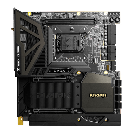
EVGA Z790 CLASSIFIED (121-RL-E798) EVGA Z790 CLASSIFIED Component Legend The EVGA Z790 CLASSIFIED Motherboard with the Intel Z790 and PCH Chipset. ® Figure 1 shows the motherboard and Figure 2 shows the back panel connectors FIGURE 1. Z790 CLASSIFIED Motherboard Layout... - Page 13 EVGA Z790 CLASSIFIED (121-RL-E798) Component Legend CPU Socket LGA1700 PCIe Slot x16/x8 Temperature Sensor Header Intel Z790 PCH PCIe Slot x8 BIOS Selector Switch CPU PWM Fan Headers (2 amp) PCIe Slot x4 CMOS Battery PWM/DC Fan Headers (2 amp)
- Page 14 EVGA Z790 CLASSIFIED (121-RL-E798) Figure 2. Chassis Rear Panel Connectors Marvell 10GbE Activity LED Status Description Speed/Link LED Status Description No Data Transmission Orange 10Gbps data rate Blinking Data Transmission Green 5Gbps/2.5Gbps/100Mbps/10Mbps data rate No Link Intel i226V Activity LED Status...
- Page 15 EVGA Z790 CLASSIFIED (121-RL-E798) Component Legend Descriptions 1. CPU Socket 1700 This is the interface for the Central Processing Unit (CPU), and supports 13 and 12 Gen. Intel Core i3, i5, i7 and i9 models compatible with the Intel ®...
- Page 16 EVGA Z790 CLASSIFIED (121-RL-E798) motherboard officially supports up to 7800MHz+ speeds. These speeds are not guaranteed, however, because Intel only certifies the speed of the Raptor Lake- ® S memory controller up to 5600MHz, and Alder Lake-S memory controller up to 4800MHz (depending upon memory configuration).
- Page 17 EVGA Z790 CLASSIFIED (121-RL-E798) 11. M.2 Socket 3 Key-M 80mm (M.2_1, M.2_2, and M.2_3) M.2 is an SSD form factor standard, which uses up to four PCIe lanes and utilizes up to Gen4 speeds. Most popularly paired with NVMe SSDs, this standard offers substantially faster transfer speeds and seek time than SATA interface standards.
- Page 18 USB, auxiliary ports that mount in the card slots, and certain devices that directly connect to the header. The USB 3.2 Gen2 Header on the Z790 CLASSIFIED is a shielded USB 3.2 Gen2 Header that supports up to 10Gb/s with USB 3.2 Gen2.
- Page 19 EVGA Z790 CLASSIFIED (121-RL-E798) 21. Front Panel Audio Connector This connector is required for recording and/or playback via the audio connectors on the front of your chassis. This header uses the standard “HD Audio” jack. Some chassis may provide two headers: one labeled HD Audio, and one labeled AC’97.
- Page 20 The ARGB header is a 3pin 5V. header with a current limit of 2A; anything above 2A will trigger overcurrent protection and lock at 2A. This header provides RGB lighting configuration via EVGA ELEET X1 within Windows, and supports up to 125 LEDs. Please see Page 42 for header specifics, and Page 94 for control options in ELEET X1.
- Page 21 PE3 – supports x16 PCIe devices or shorter. For the electrical compatibility of the Z790 CLASSIFIED, please see Page 23. *The PE2 slot can support PCIe devices up to x16-length if the M.2 heatsink is removed. However, use of an M.2 device with a tall pre-installed heatsink in the M.2_3 slot may block installation of devices longer than x4 length.
- Page 22 EVGA Z790 CLASSIFIED (121-RL-E798) Card Slots The Z790 CLASSIFIED features two x16 PCIe slots, one x4 PCIe slot, three Socket 3 Key-M M.2 80mm slots (M.2_1/M.2_2/M.2_3), and a vertical Socket 1 Key-E M.2 (Contains the WiFi/BT module). *Note: The M.2 Key-M 80mm slots are accessible only after removing the heatsink between PCIe slots PE1 and PE3.
-
Page 23: Pcie Slot Breakdown
M.2 Key-M (80mm, Bottom, M.2_3) – Gen4 x4 from Z790 PCH o This slot supports PCIe M.2 SSDs / Intel Optane ® M.2 Key-E (32mm) – Gen1 x1 from Z790 PCH o This slot is pre-installed with the EVGA Wi-Fi/BT Module - 23 -... -
Page 24: Preparing The Motherboard
Preparing the Motherboard Installing the CPU Note: EVGA strongly recommends that you turn off your power supply and discharge power by pressing the power button on your motherboard before CPU installation. This ensures the motherboard will use the correct startup procedure for all onboard devices. -
Page 25: Installing The Cpu Cooling Device
EVGA Z790 CLASSIFIED (121-RL-E798) 3. Align the notches on the CPU to the notches in the socket, and lower the processor straight down into the socket. Note: The gold triangle key on the CPU should match the triangle key on the load plate. -
Page 26: Installing System Memory (Dimms)
EVGA Z790 CLASSIFIED (121-RL-E798) Installing System Memory (DIMMs) Your Z790 CLASSIFIED has four (4) 288-pin DDR5 memory slots, and supports: Dual-channel non-ECC DDR5 memory. Up to 32GB per DIMMs. Up to 7800MHz+(OC) speeds. At least one memory slot must be populated for the board to boot and operate. -
Page 27: Installing The Motherboard
EVGA Z790 CLASSIFIED (121-RL-E798) Installing the Motherboard Proper motherboard installation involves many factors. Before installing the motherboard into your chassis, review how much space you have to install different components or cables to the motherboard, and whether it may be easier to do so prior to lowering the motherboard into the chassis for the final time. -
Page 28: Securing The Motherboard Into A System Case
EVGA Z790 CLASSIFIED (121-RL-E798) Securing the Motherboard into a System Case Please review the installation manual included with your chassis. These instructions should direct you to install standoff screws to mount the motherboard to prevent grounding, and align the board with the rear I/O opening in the chassis. Ensure that all standoffs are fully tightened prior to mounting the motherboard. - Page 29 EVGA Z790 CLASSIFIED (121-RL-E798) 1. All safe locations to secure the board to a standoff are circled in blue. 2. The motherboard should still have 1-2mm of movement before you fully-fasten the screws. Use this this tolerance to help mount graphics cards or tight-fits with other components.
-
Page 30: Installing M.2 Devices
3 (for SSDs) and Socket 1 (for WiFi/Bluetooth) – are installed differently. Below are images from an installation of an SSD on a Socket 3 Key-M 80mm slot of the Z790 CLASSIFIED. This motherboard has three (3) 80mm M.2 slots, all covered by a heatsink to provide additional cooling. - Page 31 EVGA Z790 CLASSIFIED (121-RL-E798) 2. Steps For Installing M.2 Devices When installing the M.2 device, install the gold fingers at a slight angle into the slot, and lower it so that it rests on the thermal pad. For 80mm M.2 devices: ...
- Page 32 EVGA Z790 CLASSIFIED (121-RL-E798) 3. Final Step – Reinstall the Z790 CLASSIFIED Cover for M.2 Devices Once all SSDs have been installed, reinstall the M.2 heatsink and fasten all screws. If the larger heatsink is not fully fastened, you may have difficulty installing your PCIe device in the PCIe slots.
-
Page 33: Tested Cpu
3.3 GHz P-Core Pentium® G7400 2 Cores (4 Threads) 3.7 GHz P-Core Pentium® G6900 2 Cores (2 Threads) 3.4 GHz P-Core For a list of tested CPUs, please visit https://www.evga.com/support/motherboard/ and select the EVGA Z790 CLASSIFIED from the list. - 33 -... -
Page 34: Tested M.2 Key-M
EVGA Z790 CLASSIFIED (121-RL-E798) Tested M.2 Key-M PCIE 4.0 INTERFACE Black SN850 WDS200T1X0E-00AFY0 2TB PCIE4.0 NVME M2 Samsung 980 Pro MZ-V8P500 500G PCIE4.0 NVME M2 PCIE 3.0 INTERFACE ADATA ASX8000NP-256GM-C 256G M.2 PCIE Crucial CT500P1SSD8 P1 NVME NVME M.2 500G CORSAIR MP500 CSSD-F240GBMP500 240G PCIE3.0 NVME M2... -
Page 35: Tested M.2 Key-E
EVGA Z790 CLASSIFIED (121-RL-E798) Tested M.2 Key-E - 35 -... -
Page 36: Connecting Cables
EVGA Z790 CLASSIFIED (121-RL-E798) Connecting Cables Note: The following images do not necessarily visually represent their respective headers on the EVGA Z790 CLASSIFIED. Rather, this section is designed to provide basic information about important connectors and headers pinouts. The locations of these components can be found in the Component Legend on Pages 12-14. - Page 37 Firmly plug the power supply cable into the connector and make sure it is secure. The Z790 CLASSIFIED motherboard uses a right-angle 24pin ATX connector. 6-pin PCIe The 6-pin PCIe connector present on the motherboard provides additional power to the PCIe slots, rather than pulling it all from the 24-pin main power.
- Page 38 EVGA Z790 CLASSIFIED (121-RL-E798) EPS 8-pin 12V Power (PWR , the 8-pin ATX 12V power connector provides power for the EPS PWR 8P CPU. Align the pins to the connector and press firmly until seated. The secondary EPS is optional for improved overclocking, but is not necessary for normal PC use, including gaming.
- Page 39 EVGA Z790 CLASSIFIED (121-RL-E798) Front Panel Header The front panel header on this motherboard is used to connect the following four cables: PWRLED Attach the front panel power LED cable to these two pins of the connector. The Power LED indicates the system’s status. When the system is powered on, the LED will be on.
- Page 40 EVGA Z790 CLASSIFIED (121-RL-E798) Thermal Sensor Header The external thermal sensor header is a 2-pin header that allows you to connect a thermistor cable to monitor temperatures that are not natively monitored by the motherboard. This header consists of a “Sensor” and a ground pin. Once connected, the information derived from the sensor will be viewable in BIOS and Windows.
- Page 41 EVGA Z790 CLASSIFIED (121-RL-E798) Fan Header The Z790 CLASSIFIED uses 4-pin fan headers, which are backwards compatible with 3-pin fan connectors. Fans may be controlled by PWM or DC controls. The headers have an absolute safe power limit of 2 Amp @ 12 Volts (24 Watts).
- Page 42 Amps @ 5 Volts (10 Watts) or up to 125 LEDs. This will add control options through EVGA ELEET X1 for controlling RGB LEDs. The EVGA Z790 CLASSIFIED lists these headers as “ARGB1” through “ARGB4” on the motherboard. - 42 -...
- Page 43 This motherboard contains USB 3.2 Gen2 and USB 3.2 Gen1 ports that are accessible on the rear panel of the chassis. The Z790 CLASSIFIED contains 1x 20pin internal header, which can support one USB3.2 Gen2 Type-C front-panel connector or device.
- Page 44 EVGA Z790 CLASSIFIED (121-RL-E798) The motherboard also contains 1x 19-pin internal header connectors onboard that can be used to connect an optional external bracket or device containing up to two (2) USB 3.2 Gen1 ports. Please note that these headers are often referred to as USB 3.0 internal ...
- Page 45 (2) USB 2.0 ports. The Z790 CLASSIFIED also features an onboard USB 2.0 port header, near the BIOS Select Switch. This header has a specific purpose – to allow you to flash the BIOS with a USB flash drive without an installed CPU.
- Page 46 EVGA Z790 CLASSIFIED (121-RL-E798) Front Panel Audio Header Front panel audio supports HD Audio for stereo/gaming headphones or 2.1 speakers, and a Mic. - 46 -...
- Page 47 EVGA Z790 CLASSIFIED (121-RL-E798) Drive Headers (SATA) SATA 6Gb/s is the current standard for an HDD/SSD interface. These ports provide the data interconnect for the motherboard and HDD/SSD via cable. Your drive still requires a separate power connection from your power supply.
-
Page 48: Onboard And External Buttons
EVGA Z790 CLASSIFIED (121-RL-E798) Onboard and External Buttons These onboard buttons include Reset CMOS, BIOS Update, RESET and POWER buttons. External Reset CMOS Button Reset CMOS Button The motherboard uses CMOS RAM to store your BIOS configuration. Press the Reset CMOS button shown on the right to reset the BIOS back to defaults. -
Page 49: First Boot
This is completely normal. It’s recommended to first check whether your motherboard has a BIOS update available. Go to https://www.evga.com/drivers, select the Motherboard tab, and select BIOS to see if there’s an available BIOS for your board. Download and unzip the file onto a thumb drive formatted for FAT32. - Page 50 EVGA Z790 CLASSIFIED (121-RL-E798) HDD/SSD/M.2 Setup Select “Boot” from the menu list at the top. “Boot Option #1” should show the device where you intend to install your operating system, or where you already have an installed OS. During OS installation, you may prefer to set your installation media as Boot Option #1 and your HDD/SSD/M.2 as Option #2.
-
Page 51: Ssd, Pcie Ssd, And Nvme Ssd Installation Steps
1. Install the SSD into any available PCIe slot with at least x4 Lanes available (Gen5 and Gen4 are preferred for better speed). a. The Z790 CLASSIFIED will support PCIe SSDs in all PCIe slots. 2. Attach the SSD’s mounting bracket to the back of the case. - Page 52 Legacy, press F10 to save and reboot. If Windows boots at this point, the configuration is complete. If Windows cannot boot at this point, we suggest contacting EVGA Customer Service, as further troubleshooting would be outside the scope of this manual.
-
Page 53: Configuring Raid With M.2 Ssds
RAID. Install/Verify That Your SSDs Are Ready: 1. To configure a RAID in the EVGA Z790 CLASSIFIED, you will first need to install your M.2 SSDs, as shown above on Page 30. - Page 54 EVGA Z790 CLASSIFIED (121-RL-E798) Configure RAID: 1. After enabling the VMD controller, you will see a new Advanced menu called “Intel Rapid Storage Technology”. Enter the menu. ® 2. Here, you will see all available drives, RAID volumes, and have the option to Create RAID Volume.
- Page 55 EVGA Z790 CLASSIFIED (121-RL-E798) 3. The RAID Level is set by default to RAID0 (Stripe), so you will need to change it to RAID5 (Parity). Available drives for the RAID will be listed here, along with a blank box to allow you to select whether you want each drive to be part of the RAID.
- Page 56 EVGA Z790 CLASSIFIED (121-RL-E798) Note: RAID0, RAID1, RAID5, and RAID10 are supported on the Z790 CLASSIFIED when spanned between the M.2 slots and SATA ports, but this is strongly not recommended due to the significant difference in performance and the lack of device uniformity (i.e.
-
Page 57: Internal Sata Raid Controller
EVGA Z790 CLASSIFIED (121-RL-E798) Internal SATA RAID Controller This section covers the basics of what RAID does, how RAID works, and why you may or may not want to use RAID. There are other means of creating a RAID drive on this... - Page 58 EVGA Z790 CLASSIFIED (121-RL-E798) RAID LEVELS There are three main considerations when creating a RAID array: performance, capacity, and redundancy. Fortunately, each RAID mode offered has unique characteristics that make choosing one fairly simple, based on your needs. Performance – Quite simply, which array type is the fastest? o RAID0 is considered the best performance option here.
- Page 59 EVGA Z790 CLASSIFIED (121-RL-E798) RAID0 : RAID0 is considered “Striping” or a “Striped Array.” RAID0 takes a data set and spreads it equally across two or more drives. Reading a file, for example, will be much faster if the file is spread across multiple drives and read from each drive simultaneously.
- Page 60 EVGA Z790 CLASSIFIED (121-RL-E798) RAID5 : RAID5 is a stripe with fault tolerance, which attempts to bridge the gap between speed and redundancy. It is the most all-around type of array. This array-type will reserve, essentially, a capacity size equivalent to one drive for fault-tolerance. This means that if you use four 1TB drives to create your RAID5, you will only have the capacity of three 1TB drives.
- Page 61 EVGA Z790 CLASSIFIED (121-RL-E798) RAID10 : RAID10 is a nested RAID, which is a type of RAID utilizing multiple arrays within a single configuration. This type of virtualization allows you to have an array where each node has its own level of redundancy. RAID10 is highly scalable, but this motherboard supports arrays of only four drives –...
- Page 62 EVGA Z790 CLASSIFIED (121-RL-E798) Configuring the Array 1. Attach all SATA devices you intend to use, and make sure power is attached. Power the system on. Press the “Delete” key repeatedly to enter BIOS. Once into BIOS you will need to enable the RAID function of the board.
- Page 63 EVGA Z790 CLASSIFIED (121-RL-E798) 3. Similar to the M.2 RAID instructions, set Enable VMD Controller to “Enabled”, then Save and Reboot. Upon entering the menu again, you will notice that your SATA port information will be empty. This mode includes both the RAID controls and the same options/functions/commands as AHCI.
- Page 64 EVGA Z790 CLASSIFIED (121-RL-E798) 4. Return to the SATA Configuration menu and enter the Intel Rapid Storage ® Technology menu. 5. Once in the RAID controller, you will see a list of all detected drives and a “Create RAID Volume” button. To begin, click on “Create RAID Volume.”...
- Page 65 EVGA Z790 CLASSIFIED (121-RL-E798) 7. Next, select your intended array type. Please see the bottom of Page 61 for a quick reference on different RAID levels and RAID types based on your total number of drives. For the purpose of this guide, we will make a RAID5.
- Page 66 EVGA Z790 CLASSIFIED (121-RL-E798) 10. The controller defaults the capacity to the maximum available space for the RAID. Leaving the capacity at default is recommended because reducing the size is not beneficial, except in limited cases. 11. To complete the setup process, please select “Create Volume” at the bottom of the page.
- Page 67 EVGA Z790 CLASSIFIED (121-RL-E798) 13. For OS installation, provided that the array is configured properly, the operating system will detect the array and see it as a single drive or a bootable RAID array – as opposed to several drives – and allow you to install the OS to the array without any further steps.
- Page 68 EVGA Z790 CLASSIFIED (121-RL-E798) 1. To begin the repair, select the degraded RAID volume to see your array status and all remaining drives currently configured in the RAID array. When ready, click Rebuild to start the process. 2. Next, you will see a list of all attached HDD/SSDs that can be used to rebuild the array.
- Page 69 EVGA Z790 CLASSIFIED (121-RL-E798) 3. Once the process has started you will see the status change to “Rebuilding.” Note: Completing this process in the BIOS queues the rebuilding of the array, but does not start the process until after you restart and boot into your OS. The rebuilding duration will vary –...
- Page 70 EVGA Z790 CLASSIFIED (121-RL-E798) IOMSM (Intel ® Optane ™ Memory and Storage Management) The IOMSM is the software front-end for the Intel SATA controller. IOMSM may be ® more convenient for some people due to a more detailed UI than the BIOS. It is recommended to install the RAID drivers after installing the Intel Chipset Drivers –...
- Page 71 EVGA Z790 CLASSIFIED (121-RL-E798) 1. Verify that all the drives intended for the array are present on the screen, then click “Create RAID Volume” to begin the process. For the purpose of this guide, we are using a pair of SATA SSDs to create the RAID1 array. If you were using PCIe / M.2 based NVMe drives, the same basic steps apply to both,...
- Page 72 EVGA Z790 CLASSIFIED (121-RL-E798) 2. On the next window, we will select the drives for our RAID. RAID1 requires exactly two (2) drives. Click the boxes for the two drives you wish to use in the array. There are other choices you can make on this page: a.
- Page 73 EVGA Z790 CLASSIFIED (121-RL-E798) 3. At this point, the RAID manager will summarize the choices you’ve made and request confirmation to delete data. Click Create RAID Volume to begin the process. - 73 -...
- Page 74 EVGA Z790 CLASSIFIED (121-RL-E798) 4. The build progress will be displayed on the Manage page. Once the RAID is fully built, the percentage will disappear, and your array will be shown. For further information about the array or your drives, click on the array for more details, including the option to delete or repair the array, if necessary.
- Page 75 EVGA Z790 CLASSIFIED (121-RL-E798) Repairing an array within IOMSM This section of the guide will illustrate how to repair a degraded array from within the IOMSM. For purposes of this guide, we will repair a degraded RAID1 array using a third drive plugged into the controller, but not currently in use.
- Page 76 EVGA Z790 CLASSIFIED (121-RL-E798) Click “Rebuild to another disk” to begin the repair process. On the next page, the IOMSM will explain why you need to repair your drive, warn you that you will delete any data on the spare drive, and ask you to select the disk where you want to rebuild the array.
- Page 77 EVGA Z790 CLASSIFIED (121-RL-E798) The rebuild process will begin. As with any RAID array with Fault Tolerance, the rebuilding time depends on several factors, such as array size, array type, CPU, etc. You may keep track of the rebuilding progress in the Manage tab. Once repairs are complete, the warning will disappear and the array will update to “Status: Normal.”...
- Page 78 EVGA Z790 CLASSIFIED (121-RL-E798) Partitioning and Formatting a drive Once you have created your array, either from within the BIOS or from the IOMSM, you will not initially see your array in “This PC.” This is expected, because even though you have created the array, you have not yet prepared the array to be used.
- Page 79 EVGA Z790 CLASSIFIED (121-RL-E798) After “Disk Management” loads, you’ll see a pop-up to Initialize Disk if you’ve added a new drive or created a new array. Generally, it’s recommended to select “GPT,” unless you need backwards compatibility with an old OS or PC. When you’ve made your choice, click “OK.”...
- Page 80 EVGA Z790 CLASSIFIED (121-RL-E798) Before you can assign a drive letter to a drive or array, the initialized disk must be partitioned. If you are following this guide and just initialized your drive or array, the New Simple Volume Wizard will automatically pop-up.
- Page 81 EVGA Z790 CLASSIFIED (121-RL-E798) Leave the size at default to create a partition using the entire volume of disk space, then click “Next.” Select the drive letter you want to represent this drive, then click “Next.” Note: The drive letter does NOT have to be a consecutive letter with previous drive(s).
- Page 82 EVGA Z790 CLASSIFIED (121-RL-E798) After the quick format is completed, you will see the last Window of the wizard, a summary of the process, then click “Finish.” The drive is now usable. To confirm, go back to File Explorer in Windows. Click on “This PC” and check the drives section.
-
Page 83: Fan Header Dc And Pwm Setup
EVGA Z790 CLASSIFIED (121-RL-E798) Fan Header DC and PWM setup The Z790 CLASSIFIED supports both 4-pin PWM fans and 3-pin DC fans. The motherboard uses eight 4-pin fan headers, including 2x CPU FAN (PWM), a CHA FAN (PWM/DC), a SYS FAN (PWM/DC), a PWR FAN (PWM/DC), an AUX FAN (PWM/DC), and two Pump headers (PWM/DC). - Page 84 EVGA Z790 CLASSIFIED (121-RL-E798) Once into the H/W Monitor section, you can see the temperature monitors across the top. Below the monitors, each fan is already configured in Smart mode, which means the fan controller is using a Smart curve for fan controls. Each fan can be set to a separate fan curve.
- Page 85 EVGA Z790 CLASSIFIED (121-RL-E798) Standard Smart Fan Mode To set a Smart curve, select the “Smart Fan Settings” and enter the menu. First, choose the temperature monitor the PWM controller will use to monitor for its temp information. It’s recommended to link the fan control to the CPU, which is predominantly the most important temperature in the system.
- Page 86 EVGA Z790 CLASSIFIED (121-RL-E798) In Standard Mode, there are four tiers of temp control. At Level 4, we recommend to set the fan speeds to Max. Feel free to create your own profile to meet your noise and cooling needs. Make sure, however, to stay 5-10C below the Max safe load temp for your processor, which is listed on Intel’s website.
- Page 87 Using the ELEET X1 Software Suite EVGA ELEET X1 is a monitoring and tuning software designed for EVGA motherboards, which is available on the included USB drive and the EVGA website at https://www.evga.com/eleetx1. After installation, run ELEET X1. The left-hand side of the display contains system information about your motherboard, including the CPU, per-core CPU clock speed/voltage/temperature, and memory information.
- Page 88 EVGA Z790 CLASSIFIED (121-RL-E798) As seen above, there are options for multiple voltages, and two options for your CPU Vcore: Adaptive and Override voltages. Adaptive allows for a tighter voltage profile to keep voltage and heat to a minimum, while Override is more of a brute-force method of setting your voltage.
- Page 89 EVGA Z790 CLASSIFIED (121-RL-E798) Other voltages do not utilize the Adaptive or Override voltage settings. Instead, these use a pulldown menu to select preset voltages, as shown above. The voltages for these components are set by detection during POST, and ELEET X1 will open the pulldown to the currently detected voltage.
- Page 90 EVGA Z790 CLASSIFIED (121-RL-E798) The “Memory” tab allows for Real Time Memory overclocking on the Z790 CLASSIFIED, although this function is limited and determined by the installed processor. In other words, not all processors will be able to adjust memory timings on this page.
- Page 91 EVGA Z790 CLASSIFIED (121-RL-E798) The next tab is “Monitoring,” which contains real-time system information of voltages, temperatures, and fan speed information. Please note that all readings on this page are pulled from motherboard sensors, and change dynamically. Temperatures and voltages are measured at fixed intervals, which can often make the readings appear to jump back and forth.
- Page 92 EVGA Z790 CLASSIFIED (121-RL-E798) The “System” tab provides more detailed information on the motherboard, CPU, and memory. Here, you can find the motherboard specs and BIOS date and version. - 92 -...
- Page 93 EVGA Z790 CLASSIFIED (121-RL-E798) Additional CPU details are provided, including the Stepping, Revision, Instructions, and Cache layout. Lastly, additional memory information is available for secondary memory timings, as well as the type and number of channels being used. - 93 -...
- Page 94 EVGA Z790 CLASSIFIED (121-RL-E798) Onboard ARGB and lighting connected to the ARGB headers can be controlled through the LED tab. Users can select different modes/patterns of lighting based on the header type and the number of LEDs connected through the ARGB headers. The LED lighting can be synced together by enabling the “link”...
- Page 95 EVGA Z790 CLASSIFIED (121-RL-E798) The Z790 CLASSIFIED motherboard includes a BT/Wi-Fi module, along with a new antenna design that provides extended features. The Wi-Fi page will display typical information about your wireless connection and your signal strength, including your Access Point name, wireless band, and wireless version.
- Page 96 This has been the ELEET X1 utility overview, which should give you a solid start to understanding and using the ELEET X1 software suite. *EVGA ELEET X1 is still undergoing final testing and design modifications at the time of this manual’s printing. Final GUI design, menus, and functionality may be subject to change.
-
Page 97: Installing Drivers And Software
User’s Manual Windows 11/10 Driver Installation 1. Insert the USB flash drive included in your EVGA Z790 CLASSIFIED motherboard kit into a USB port on the motherboard or from your chassis. 2. Double-click the “Autorun” application file. - 97 -... - Page 98 5. The Driver Utility Screen also contains helpful links to give you more information about your new EVGA motherboard and additional resources to get started. The Z790 CLASSIFIED manual is available through this utility and within the USB flash drive directly.
-
Page 99: Warranty And Overclocking
Of course, there are some limitations to our warranties. If an EVGA motherboard or graphics card sustains physical or liquid damage (i.e. damage to the PCB or components), the warranty is void. -
Page 100: Troubleshooting
When complete, the motherboard will automatically shut down. Power on the motherboard to go into the motherboard BIOS. g. When you see the Z790 CLASSIFIED splash screen, you will likely see a checksum error message. Click Yes to continue. Confirm that the BIOS has been updated to the latest version by checking the BIOS version (located in the bottom-right of the screen) with the BIOS version you downloaded. - Page 101 EVGA Z790 CLASSIFIED (121-RL-E798) B. To flash from within the Z790 CLASSIFIED BIOS: a. Download the latest motherboard BIOS, and unzip the file to your desktop. b. Move the extracted folder onto your USB flash drive. c. Reboot the motherboard.
-
Page 102: Flashing The Bios Without A Cpu
1. Locate or prepare a USB disk formatted to FAT32. The USB disk included with this motherboard is already formatted to FAT32. 2. Download your intended BIOS from https://www.evga.com/drivers. 3. Unzip the file. Go into the extracted folder, and rename the .bin file to EVGAZ798.bin. - Page 103 EVGA Z790 CLASSIFIED (121-RL-E798) The flash process may take up to 7 minutes, and the motherboard will automatically reboot. If you have not installed a CPU and at least one 8-pin CPU power connector, the POST LED will stop at an error code. If this occurs, turn off the motherboard and install any remaining hardware components before booting again.
-
Page 104: Ssd / Hdd Is Not Detected
EVGA Z790 CLASSIFIED (121-RL-E798) SSD / HDD is not detected If you’ve physically installed a drive that is not detected in Windows, by Windows setup, or within BIOS, please try the following steps. Component troubleshooting is primarily accomplished through process of elimination testing to deduce a faulty component or a bad connection. - Page 105 EVGA Z790 CLASSIFIED (121-RL-E798) the issue. If one or more of the cables test bad with a different device, then replacing the cable(s) should resolve the issue. M.2 devices are much simpler to troubleshoot. M.2 devices are installed at a slight angle, gently lowered until parallel with the motherboard, and then fastened into place.
-
Page 106: Using The Post Code Indicator To Troubleshoot
PCIe 8- pin into the EPS connector, which may cause irreparable damage to the motherboard or the CPU. For the Z790 CLASSIFIED, inserting an 8-pin PCIe connector will likely damage the PCB due to the right-angle connectors. -
Page 107: System Does Not Post, And Multi-Function Display Reads "55
“Reset CMOS” button. The system will power on when the Reset CMOS button is pressed. This should allow the system to boot up. When you see the EVGA Z790 CLASSIFIED screen, press “Delete” to enter BIOS, set the XMP profile (instructions are covered in first boot section on Page 49), save and exit, and the system will reboot. -
Page 108: Have A Question Not Covered Above, Or Want Some Online Resources
EVGA Z790 CLASSIFIED (121-RL-E798) Have a question not covered above, or want some online resources? If you have any issues or questions, you can find a lot of valuable help and information on our website, including contact information for our top-notch Technical Support/Customer Service. -
Page 109: Multi-Function Display Post Debug Led
EVGA Z790 CLASSIFIED (121-RL-E798) Multi-function Display POST Debug LED The Multi-function Display’s functions include providing two-digit diagnostic POST codes. These POST codes show system boot status and its behavior can help to determine why the system may be failing to boot. This LED is extremely useful as a debugging tool during troubleshooting situations. -
Page 110: Multi-Function Led Indicator
EVGA Z790 CLASSIFIED (121-RL-E798) Multi-function LED indicator EVGA Z790 CLASSIFIED board is equipped with a versatile display to allow real-time monitoring of system status during and after the BIOS POST process. The operating mode can be configured in the BIOS Setup in the Advanced menu, and then H/W Monitor Configuration. - Page 111 EVGA Z790 CLASSIFIED (121-RL-E798) - 111 -...
-
Page 112: Post Beep Codes
EVGA Z790 CLASSIFIED (121-RL-E798) POST Beep Codes POST beeps are used in conjunction with the Multi-function Display to help determine the root cause when your system fails to boot. However, modern motherboards also use the speaker to convey helpful information, such as USB device detection. As a result,... -
Page 113: Post Codes
Multi-function Display with Temperature Monitor This section provides the AMI POST Codes for the EVGA Z790 CLASSIFIED Motherboard during system boot up. The POST Codes are displayed on the Multi-function Display readout located directly on the motherboard and can be used to help troubleshoot pre-boot issues. - Page 114 EVGA Z790 CLASSIFIED (121-RL-E798) Microcode not loaded PEI Core is started 11-14 Pre-memory CPU initialization is started 15-18 Pre-memory North Bridge initialization is started 19-1C Pre-memory South Bridge initialization is started 1D-2A OEM pre-memory initialization codes Memory initialization. Serial Presence Detect (SPD) data reading Memory initialization.
- Page 115 EVGA Z790 CLASSIFIED (121-RL-E798) reset PPI is not available 5C-5F Reserved for future AMI error codes S3 Resume is stared (S3 Resume PPI is called by the DXE IPL) S3 Boot Script execution Video repost OS S3 wake vector call...
- Page 116 EVGA Z790 CLASSIFIED (121-RL-E798) CSM initialization 7A–7F Reserved for future AMI DXE codes 80–8F OEM DXE initialization codes Boot Device Selection (BDS) phase is started Driver connecting is started PCI Bus initialization is started PCI Bus Hot Plug Controller Initialization...
- Page 117 EVGA Z790 CLASSIFIED (121-RL-E798) Legacy Boot event Exit Boot Services event CPU Memory controller configuration Runtime Set Virtual Address MAP End iMC init Memory training Memory training Memory training / timing training Memory training Memory training B8-BF Memory training / DRAM final configuration C0–CF OEM BDS initialization codes...
-
Page 118: Evga Glossary Of Terms
DMI – Direct Memory Interface DP – Display Port DRAM - Dynamic random access memory DVI – Digital Video Interface ELEET X1 – EVGA motherboard monitoring and tuning software GHz – Gigahertz GPU – Graphics Processing Unit GUI – Graphical User Interface HDD –... - Page 119 EVGA Z790 CLASSIFIED (121-RL-E798) IEEE - Institute of Electrical and Electronics Engineers IGP - Integrated Graphics Processors IMC – Integrated memory controller IOH – Input/Output Hub IRQ - Interrupt Request JBOD - Just a Bunch of Disks JEDEC - Joint Electron Device Engineering Council...
- Page 120 EVGA Z790 CLASSIFIED (121-RL-E798) POST – Power On Self-Test PWM – Pulse Width Modulation QOS – Quality of Service RAID - Redundant Array of Inexpensive Disks RAM – Random Access Memory ROM – Read Only Memory RGB - Red Green Blue SATA - Serial Advanced Technology Attachment SAS –...
-
Page 121: Compliance Information
US and other countries. Other company, products and service names may be trademarks or service marks of others. EVGA reserves the right to terminate this license if there is a violation of its terms or default by the Original Purchaser. Upon termination, for any reason, all copies of Software and materials must be immediately returned to EVGA and the Original Purchaser shall be liable to EVGA.com...
Need help?
Do you have a question about the Z790 CLASSIFIED and is the answer not in the manual?
Questions and answers