Table of Contents
Advertisement
Quick Links
Advertisement
Table of Contents

Subscribe to Our Youtube Channel
Related Manuals for Goulds Pumps 3501


Summary of Contents for Goulds Pumps 3501
- Page 1 Installation, Operation, and Maintenance Instructions 3501...
-
Page 3: Table Of Contents
4.3.1 Check rotor axial clearance......................25 4.3.2 Lubricating bearings........................25 4.3.3 Shaft sealing ..........................26 4.4 Starting mixer ............................26 4.5 Operation..............................27 4.5.1 General considerations ......................... 27 4.5.2 Operating at reduced capacity ...................... 27 3501 Installation, Operation, and Maintenance Instructions... - Page 4 7.1.1 Most desirable spare parts......................56 7.1.2 Recommended spare parts......................56 7.1.3 Minimum recommended spare parts..................... 56 7.2 3501 Mixer cross sectional and parts list with materials of construction ..........57 7.3 How to order............................58 7.4 Emergency service..........................58...
- Page 5 ITT - Goulds Pumps shall not be liable for physical injury, damage or delays caused by a failure to ob- serve the instructions for Installation, Operation, and Maintenance contained in this manual.
-
Page 6: Safety
ITT Goulds pumps will provide safe, trouble-free service when properly installed, maintained, and operat- Safe installation, operation, and maintenance of ITT Goulds Pumps equipment are an essential end user responsibility. This Pump Safety Manual identifies specific safety risks that must be considered at all times during product life. -
Page 7: Safety
Trapped liquid can rapidly expand and result in a violent explosion and injury. ITT Goulds Pumps will not accept responsibility for physical injury, damage, or delays caused by a failure to observe the instructions for installation, operation, and maintenance contained in this Pump Safety Manual or the current IOM available at http://www.gouldspumps.com/literature. - Page 8 Lift equipment only at specifically identified lifting points or as instructed in the current IOM. Current manuals are available at www.gould- spumps.com/literature_ioms.html or from your local ITT Goulds Pumps sales representative. Note: Lifting devices (eyebolts, slings, spreaders, etc.) must be rated, selected, and used for the entire load being lifted.
- Page 9 WARNING Never apply heat to remove an impeller. The use of heat may cause an explo- sion due to trapped fluid, resulting in severe physical injury and property dam- age. 3501 Installation, Operation, and Maintenance Instructions...
-
Page 10: Parts
1.5 Parts The use of genuine Goulds parts will provide the safest and most reliable operation of your pump. ITT Goulds Pumps ISO certifica- tion and quality control procedures ensure the parts are manufac- tured to the highest quality and safety levels. -
Page 11: General Information
- English on page 10 Figure 2: Mixer casing tag - metric on page Bearing Frame Tag - provides recommended type of lubrication the mixer, see Figure 3: Bearing frame tag on page 3501 Installation, Operation, and Maintenance Instructions... -
Page 12: Receiving The Mixer
2.3.1 Storage Requirements Short Term: (Less than 6 months): Goulds normal packaging procedure is designed to protect the mixer during shipping. Upon receipt store in a covered and dry location. 3501 Installation, Operation, and Maintenance Instructions... -
Page 13: Handling
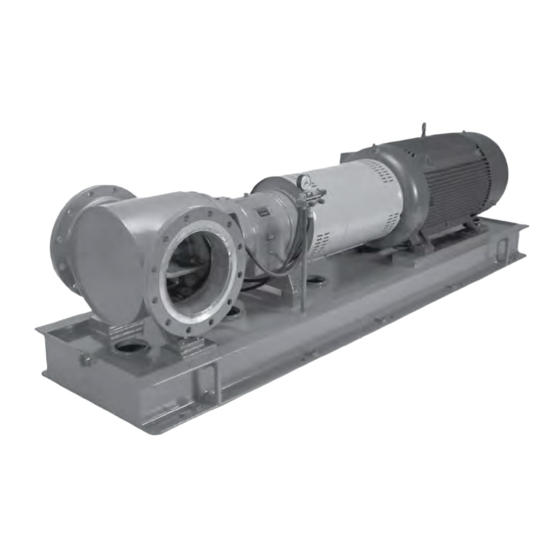
Baseplate mounted units are moved with slings under the mixer casing flanges and driver. See Figure 4: Bare mixer on page Figure 5: Baseplate mounted on page 12, and Figure 6: Baseplate and driv- er on page 12, for examples of proper lifting techniques. Figure 4: Bare mixer 3501 Installation, Operation, and Maintenance Instructions... - Page 14 2.3 Receiving the mixer Figure 5: Baseplate mounted Figure 6: Baseplate and driver 3501 Installation, Operation, and Maintenance Instructions...
-
Page 15: Installation
Carefully lower baseplate onto foundation bolts. Level baseplate to within 3.2 mm (.125in.) over length of the baseplate and to within 1.5 mm (.060 in.) over the width of the base by adjusting wedges. 3501 Installation, Operation, and Maintenance Instructions... -
Page 16: Alignment And Alignment Procedure
NOTICE: Proper alignment is the responsibility of the installer and user of the unit. Accurate alignment of the equipment must be attained. Trouble-free operation can be accomplished by following these procedures. 3501 Installation, Operation, and Maintenance Instructions... -
Page 17: Alignment Checks
During the installation phase, however, it is necessary to set the parallel alignment in the vertical direc- tion to a different criteria due to differences in expansion rates of the mixer and driver. For Model 3501, the Cold Setting of Parallel Vertical Alignment table shows recommended preliminary (cold) settings for electric motor driven mixers based on different pumpage temperatures. -
Page 18: Measurement
Zero indicator A on left side of coupling half Y, 90° from top dead center (9 o'clock). Rotate indicators through top dead center to the right side, 180° from the start (3 o'clock). Ob- serve needle and record reading. 3501 Installation, Operation, and Maintenance Instructions... -
Page 19: Parallel Alignment
Positive Reading - Coupling half X is higher than coupling half Y. Correct by adding shims of thickness equal to half of the indicator reading from each driver foot, see below. Figure 14: Positive reading correction 3501 Installation, Operation, and Maintenance Instructions... -
Page 20: Complete Alignment
Zero indicators A and P on the left side of coupling half Y, 90° from top dead center (9 o'clock). Rotate indicators through top dead center to the right side, 180° from the start (3 o'clock). Ob- serve the needle, measure and record the reading. 3501 Installation, Operation, and Maintenance Instructions... -
Page 21: Grout Baseplate
Pour grout through grout hole in baseplate, up to level of dam. Remove air bubbles from grout as it is poured by puddling, using a vibrator, or pumping the grout into place. Non-shrink grout is recom- mended. Allow grout to set. Fill remainder of baseplate with grout. Remove air as before: 3501 Installation, Operation, and Maintenance Instructions... -
Page 22: Alignment Check
The piping should be arranged to allow mixer flushing prior to removal of the unit on services handling corrosive liquids. Carefully clean all pipe parts, valves and fittings, and mixer branches prior to assembly. 3501 Installation, Operation, and Maintenance Instructions... -
Page 23: Inlet Piping
Is part of the mixer design package. Valves • Control valve is typically before the mixer. • If additional back pressure is required, the control valve may be after the mixer. • Shut off valves should be after the mixer. 3501 Installation, Operation, and Maintenance Instructions... -
Page 24: Gas Mixing
Now install the top adjusting nut and jam nut. Tighten finger tight. Repeat steps one through four for all the spring assemblies. Once all the springs have been installed, lower the unit on to the foundation pads. 3501 Installation, Operation, and Maintenance Instructions... - Page 25 NOTICE: Suction and discharge piping must be individually supported. The spring mounted baseplates are designed to support piping loads developed by thermal expansion only. 3501 Installation, Operation, and Maintenance Instructions...
-
Page 26: Operation
Lock out power to driver. 4.3 Couple mixer and driver WARNING: Lock out driver power to prevent accidental rotation and physical injury. Install and lubricate coupling per manufacturer’s instructions. Install coupling guard. 3501 Installation, Operation, and Maintenance Instructions... -
Page 27: Check Rotor Axial Clearance
(Fig. 21). Fill the oiler bottle with oil and replace in the oiler housing. Oil reservoir in bearing frame is filled when oil remains visible in the bottle. Several fillings of the bottle may be required. 3501 Installation, Operation, and Maintenance Instructions... -
Page 28: Shaft Sealing
(15 PSI) above seal chamber pressure. Injection rate should be 4-8 liters per minute (1-2 gallons per minute). 4.4 Starting mixer Make sure inlet valve and any recirculation or cooling lines are open. Make sure outlet valve is open as dictated by system conditions. Start Driver. 3501 Installation, Operation, and Maintenance Instructions... -
Page 29: Operation
Run the unit under actual operating conditions for a sufficient length of time to bring the mixer and driver up to operating temperature. Shut down unit and lock out driver to prevent accidental rotation. 3501 Installation, Operation, and Maintenance Instructions... -
Page 30: Interlocks
In C/D stage, the mixer material is titanium and dry chlorine will destroy this material! • Chlorine has to be mixed with chlorine dioxide or water before it enters into the chemical addition pipe of the mixer. 3501 Installation, Operation, and Maintenance Instructions... -
Page 31: Preventative Maintenance
5.3.1 Oil lubricated bearings Oil lubricated bearings must be lubricated at the job site. Remove fill plug (408H) and add oil until level is at the center of the sight glass (319). Replace fill plug. 3501 Installation, Operation, and Maintenance Instructions... - Page 32 82°C (180° F) 82°C (180° F) ISO Grade VG 68 VG 100 Approx. SSU at 38°C (100°F) DIN 51517 C100 Kinematic viscosity at 40°C (105°F) mm2/sec Acceptable Oils Exxon Teresstic EP 68 Chevron GTS Oil 68 3501 Installation, Operation, and Maintenance Instructions...
-
Page 33: Grease Lubricated Bearings
When regreasing, there is danger of impurities entering the bearing housing. The grease con- tainer, the greasing device, and fittings must be clean. Wipe dirt from grease fittings. Remove two (2) grease relief plugs (408C). 3501 Installation, Operation, and Maintenance Instructions... - Page 34 For operating temperatures above 110°C (230°F) the bearings should be lubricated with a high tempera- ture grease. Mineral oil greases should have oxidation stabilizers and a consistency of NLGI 3. 3501 Installation, Operation, and Maintenance Instructions...
-
Page 35: Maintenance Of Shaft Seals
A change in mixer performance may be noted over time by a decrease in brightness. Performance can usually be renewed by adjusting the rotor clearance. The total axial adjustment of the rotor between the 3501 Installation, Operation, and Maintenance Instructions... -
Page 36: Dial Indicator Method
Remove coupling guard. Loosen jam nuts (423B) on adjuster bolts (371A) and back bolts out about two turns. Tighten locking bolts (370C) evenly, drawing bearing housing (134A) towards frame (228) until rotat- ing assembly bottoms out. 3501 Installation, Operation, and Maintenance Instructions... -
Page 37: Mixer Washdown
5.8 Mixer washdown These mixers are designed to prevent liquid from entering the bearing frame. Care should be taken, however, to avoid spraying a high pressure stream directly at the labyrinth frame seals. 3501 Installation, Operation, and Maintenance Instructions... - Page 38 Check lubrication and cooling lines. Shaft sleeve scored. Remachine or replace as required. Motor requires excessive power. Liquid heavier than expected. Check specific gravity and viscosity. Rotating parts bind. Check internal wearing parts for proper clearances. 3501 Installation, Operation, and Maintenance Instructions...
-
Page 39: Disassembly And Reassembly
Lock out power supply to driver. Shut off all valves controlling flow to and from mixer. Drain liquid from piping, flush mixer if necessary. Disconnect all auxiliary tubing and piping. Remove coupling guard. Disconnect coupling. 3501 Installation, Operation, and Maintenance Instructions... -
Page 40: Disassembly
Remove six (6) casing bolts (370A, casing- to-seal chamber) and eight (8) casing bolts (469Z, frame-to-seal chamber to casing). Figure 26: Placement of sling hoist Use jack bolts (418) to remove the back pullout. 3501 Installation, Operation, and Maintenance Instructions... -
Page 41: Removal Of Rotor
Another method of removing the rotor is using a rotor puller. Figure 28: Rotor puller WARNING: Do not use heat on the rotor to help remove, severe bodily injury could occur. CAUTION: In order to prevent rotor damage, use pry points under rotor vanes. 3501 Installation, Operation, and Maintenance Instructions... -
Page 42: Removal Of Taperbore™ Plus Seal Chamber And Mechanical Seal
Remove the four (4) hex nuts (355) and washers (354) from the seal gland plate. Loosen the set screws on the seal drive collar and slide the mixer sleeve (126) out of the seal. Service per the seal manufacturer’s instructions. 3501 Installation, Operation, and Maintenance Instructions... -
Page 43: Disassembly Of Bearing Frame
Support both ends of shaft to prevent rotating element from dropping when bearings are disen- gaged from bores. Radial end cover (109A) is installed permanently at factory and should not require removal. Remove thrust bearing retainer ring (253B) by removing socket head cap screws (236A) (Fig. 34). 3501 Installation, Operation, and Maintenance Instructions... -
Page 44: Inspections
Inspect leading and trailing edges of vanes for pitting, and erosion or corrosion damage. Inspect keyway and bores for damage. 6.10 Seal chamber Thoroughly clean gasket surfaces and fits to remove rust and debris. Inspect surface for pitting, and erosion or corrosion damage. 3501 Installation, Operation, and Maintenance Instructions... -
Page 45: Bearing Frame
Table 9: Bearing Sizes Group Thrust bearing Radial bearing 7312BECBY NUP312ECP 7315BECBY NUP314ECP 7318BECBY NUP317ECP 6.12 Reassembly Specifications Table 10: Model 3501 Fastener Information Item Part Name Group Construc- Goulds Part No. Thread Size Hex Torque Value tion Size See Notes1- Mixer... - Page 46 A02818A125 2440 M16 x 2.00 Carbon A02818A144 2442 M20 x 2.50 Steel 316ss A02818A144 2440 M20 x 2.50 Hex Head Cap Screw A02818A89 2442 M10 x 1.50 – Jacking L and XL A02818A107 2442 M12 x 1.75 3501 Installation, Operation, and Maintenance Instructions...
-
Page 47: Reassembly Of Bearing Frame
Do not use a flame to heat bearings, this will damage bearing surfaces. Figure 35: Bearing frame reassembly NOTICE: Refer to Table 10: Model 3501 Fastener Information on page 43 for the torque values for all fasteners. After heating, install radial bearing (409) onto shaft ensuring spacing ring is placed between shaft shoulder and inner race (Fig. - Page 48 (Figs. 36 and 37). NOTICE: There will be a gap of approximately 3-4 mm (.12-16 in.) between retainer and housing. 12. Prepare bearing frame (228) for either oil or grease oil lubrication as follows: 3501 Installation, Operation, and Maintenance Instructions...
- Page 49 14. Tap radial end cover (109A) in place using a soft blow hammer. 15. Lightly lubricate bores of bearing frame (228), outer diameters of radial bearing (409) and thrust bearing housing (134A), and housing O-ring (496) with compatible oil or grease (Fig. 40). 3501 Installation, Operation, and Maintenance Instructions...
- Page 50 Figure 40: Oil and grease lubrication housing orientation Align holes in coupling guard end plate to bearing housing to frame holes in thrust bearing housing (134A) and install hex cap bolts (370C) (Fig. 42). Figure 41: Coupling guard end plate 3501 Installation, Operation, and Maintenance Instructions...
- Page 51 If equipped with a sight oiler (251), install on left side of bearing frame (228) as viewed from coupling end. 27. Grease Lubrication Install two grease fittings (193H) into bearing frame (228) as follows, based on viewing from coupling end (Fig. 44): 3501 Installation, Operation, and Maintenance Instructions...
- Page 52 28. If equipped with an oil cooler, install cooler assembly into bearing frame (228), based on viewing from coupling end as follows (Fig. 45): Figure 43: Oil cooler assembly Install one tube fitting with straight bore on left side of frame. 3501 Installation, Operation, and Maintenance Instructions...
-
Page 53: Reassembly Of Taperbore™ Plus Seal Chamber And Mechanical Seal
Refer to mechanical seal drawing. Tighten gland nuts (355) evenly. Tighten set screws in drive collar while setting clips are engaged. Remove setting clips. 6.15 Installation of rotor Install shaft key (178) on shaft (122) (Fig. 47). 3501 Installation, Operation, and Maintenance Instructions... -
Page 54: Installation Of Casing Foot And Alignment Pin
6.16 Installation of casing foot and alignment pin NOTICE: Model 3501 6" and 8" mixers require a casing foot (131). The 12" mixer does not. Model 3501 8" mixers require an alignment pin on the inlet flange to ensure that the chemical injection pipe (174) is properly oriented. -
Page 55: Installation Of Back Pull-Out Assembly
Install hex cap screws (370F) and tighten to torque value in Table 10: Model 3501 Fastener Infor- mation on page For 8" mixers, degrease threads in casing (100) inlet flange, and apply ND Industries VIBRA-TITE thread sealing compound to threads on alignment pin. - Page 56 12. Lubricate bearing frame assembly with oil or grease as described in Operation and Preventive Maintenance sections. 13. Rotate shaft (122) by hand to assure free rotation. 14. Reinstall coupling hub. 15. Align mixer. 16. Reconnect coupling. 17. Install coupling guard (Fig. 49). 3501 Installation, Operation, and Maintenance Instructions...
- Page 57 For pumps supplied with cartridge mechanical seals, be sure the set screws in the seal locking ring have been tightened and the centering clips removed prior to startup. Failure to take these steps could result in damage to the mechanical seal or shaft sleeve. 3501 Installation, Operation, and Maintenance Instructions...
-
Page 58: Spare Parts
• Shaft Sleeve, item 126 • Bearing, items 112 and 409 • Bearing Locknut, item 136 • Bearing Lockwasher, item 382 • Rotor Nut, item 304 • Gaskets and O-rings required for one mixer 3501 Installation, Operation, and Maintenance Instructions... -
Page 59: 3501 Mixer Cross Sectional And Parts List With Materials Of Construction
7.2 3501 Mixer cross sectional and parts list with materials of construction 7.2 3501 Mixer cross sectional and parts list with materials of construction Mixer Cross Sectional Table 11: 3501 Mixer parts list with materials of construction Item No. Qty Per... -
Page 60: How To Order
Quantities of Item Numbers 370C, 371A and 423B are 3 for M group and 4 for L and XL groups. 7.3 How to order When ordering parts call 1-800-446-8537 or your local Goulds Representative. 7.4 Emergency service Emergency parts service is available 24 hours/day, 365 days/year. 3501 Installation, Operation, and Maintenance Instructions... - Page 61 7.4 Emergency service Call 1-800-446-8537 Visit our Web site at http://www.gouldspumps.com 3501 Installation, Operation, and Maintenance Instructions...
- Page 62 Visit our website for the latest version of this document and more information: www.gouldspumps.com ITT - Goulds Pumps 240 Fall Street Seneca Falls, NY 13148 Form IOM.3501.en-us.2022-07 ©2022 ITT Corporation The original instruction is in English. All non-English instructions are translations of the original instruction.
Need help?
Do you have a question about the 3501 and is the answer not in the manual?
Questions and answers