Hologic Selenia Dimensions Site Planning & Installation Manual
Digital mammography system
Hide thumbs
Also See for Selenia Dimensions:
- User manual (168 pages) ,
- Instructions for use manual (146 pages) ,
- User manual (152 pages)
Table of Contents
Advertisement
Advertisement
Table of Contents

Related Manuals for Hologic Selenia Dimensions


Summary of Contents for Hologic Selenia Dimensions
- Page 3 Selenia Dimensions ® ® Digital Mammography System Digital Tomosynthesis System Site Planning and Pre-Installation Guide Part Number MAN-03169 Revision 005 December 2017...
- Page 4 Hologic, 3Dimensions, Dimensions, Selenia, Affirm, FAST Paddle, SecurView, SecurXchange, and associated logos are trademarks and/or registered trademarks of Hologic, Inc., and/or its subsidiaries in the United States and/or other countries. All other trademarks, registered trademarks, and product names are the property of their respective owners.
-
Page 5: Table Of Contents
Selenia Dimensions System Site Planning and Pre-Installation Guide Table of Contents Table of Contents List of Figures ________________________________________________________________ vii List of Tables __________________________________________________________________ ix 1: Introduction and General Information ___________________________________________1 Introduction ................................1 System Description ..............................2 1.2.1 Tubestand Overview ..........................2 1.2.2... -
Page 7: List Of Figures
Selenia Dimensions System Site Planning and Pre-Installation Guide Table of Contents List of Figures Figure 1: Tubestand for Selenia Dimensions System ....................2 ® ® Figure 2: Acquisition Workstations ..........................3 Figure 3: Tubestand (Gantry with C-arm) Measurements ..................15 Figure 4: Universal Acquisition Workstation Measurements ................... -
Page 9: List Of Tables
Selenia Dimensions System Site Planning and Pre-Installation Guide Table of Contents List of Tables Table 1: Electronic Emissions ............................10 Table 2: Electromagnetic Immunity Part 1 ........................10 Table 3: Electromagnetic Immunity Part 2 ........................12 Table 4: Separation Distances for RF Equipment ......................13 Table 5: Room Requirements ............................ -
Page 11: 1: Introduction And General Information
Selenia Dimensions System Site Planning and Pre-Installation Guide Chapter 1: Introduction and General Information Chapter 1 Introduction and General Information Introduction This guide, an aid for the Installation Coordinator responsible for site planning and preparation, contains all product information, specifications, and directions necessary for determining the installation requirements. -
Page 12: System Description
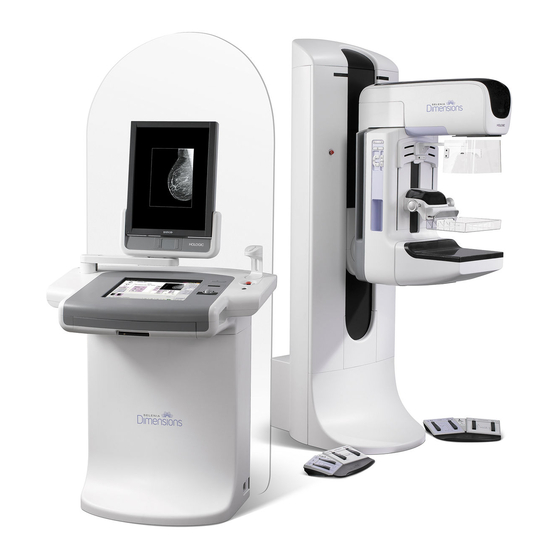
Selenia Dimensions System Site Planning and Pre-Installation Guide Chapter 1: Introduction and General Information System Description 1.2.1 Tubestand Overview Figure 1: Tubestand for Selenia Dimensions System ® ® Figure Legend 1. Tubestand (Gantry and C-arm) 2. Gantry 3. C-arm (Tube Arm and Compression Arm) 4. -
Page 13: Acquisition Workstation Overview
Selenia Dimensions System Site Planning and Pre-Installation Guide Chapter 1: Introduction and General Information 1.2.2 Acquisition Workstation Overview Figure 2: Acquisition Workstations Figure Legend Universal Acquisition Workstation Premium Acquisition Workstation Mobile Acquisition Workstation Standard Acquisition Workstation MAN-03169 Revision 005 Page 3... -
Page 14: System Location Considerations
Selenia Dimensions System Site Planning and Pre-Installation Guide Chapter 1: Introduction and General Information System Location Considerations Site Planning Checklist on page 25 is set up to assist you with the following topics when selecting a location for the system: System component sizes and weight •... -
Page 15: Safety
Selenia Dimensions System Site Planning and Pre-Installation Guide Chapter 1: Introduction and General Information Safety 1.4.1 Isolation Integrity WARNING! To correctly isolate the system, attach only approved accessories or options to the system. Only approved personnel can change the connections. -
Page 16: The X-Ray Interlock
Selenia Dimensions System Site Planning and Pre-Installation Guide Chapter 1: Introduction and General Information 1.4.4 The X-ray Interlock The X-ray Interlock connector at the rear of the Gantry provides a normally closed (NC) contact (5V 10mA) for the Acquisition Workstation. When an external interlock is used (for example a door or shield switch), a contact opens and an exposure cannot take place. -
Page 17: Compliance
Selenia Dimensions System Site Planning and Pre-Installation Guide Chapter 1: Introduction and General Information Compliance This section describes the mammography system compliance requirements and the responsibilities of the manufacturer. 1.5.1 Compliance Requirements The manufacturer has the responsibility for the safety, reliability, and performance of this equipment with the following provisions: •... -
Page 18: Compliance Statements
Selenia Dimensions System Site Planning and Pre-Installation Guide Chapter 1: Introduction and General Information Caution: Changes or modifications not expressly approved by Hologic could void your authority to operate the equipment. Caution: This equipment has been tested and found to comply with the limits for a Class A digital device, pursuant to part 15 of the FCC Rules. - Page 19 Selenia Dimensions System Site Planning and Pre-Installation Guide Chapter 1: Introduction and General Information • IEC 60601-1-1Ed. 2.0:2000 Medical Electrical Equipment - Part 1-1: General Requirements for Safety - Collateral Standard: Safety Requirements for Medical Electrical Systems • IEC 60601-1-2 Ed. 3.0:2007 Medical Electrical Equipment – Part 1-2: General Requirements for Basic Safety and Essential Performance - Collateral Standard: Electromagnetic Compatibility –...
-
Page 20: Electromagnetic Compatibility
Selenia Dimensions System Site Planning and Pre-Installation Guide Chapter 1: Introduction and General Information 1.5.3 Electromagnetic Compatibility This section provides information about the electromagnetic compatibility of system per IEC 60601-1-2. Table 1: Electronic Emissions Electromagnetic Emissions The system is intended for use in the electromagnetic environment specified below. The customer or the user of the system should assure that it is used in such an environment. - Page 21 Selenia Dimensions System Site Planning and Pre-Installation Guide Chapter 1: Introduction and General Information Table 2: Electromagnetic Immunity Part 1 Electromagnetic Immunity – Part 1 Voltage dips, short <5% Ut (>95 % dip in <5% Ut (>95 % dip in...
-
Page 22: Table 3: Electromagnetic Immunity Part 2
Selenia Dimensions System Site Planning and Pre-Installation Guide Chapter 1: Introduction and General Information Table 3: Electromagnetic Immunity Part 2 The system is intended for use in the electromagnetic environment specified below. The customer or the user of the system should assure that it is used in such an environment. -
Page 23: Table 4: Separation Distances For Rf Equipment
Selenia Dimensions System Site Planning and Pre-Installation Guide Chapter 1: Introduction and General Information Table 3: Electromagnetic Immunity Part 2 The system is intended for use in the electromagnetic environment specified below. The customer or the user of the system should assure that it is used in such an environment. -
Page 25: 2: Specifications And Reference Information
Selenia Dimensions System Site Planning and Pre-Installation Guide Chapter 2: Specifications and Reference Information Chapter 2 Specifications and Reference Information Product Measurements 2.1.1 Tubestand (Gantry with C-Arm) Figure 3: Tubestand (Gantry with C-arm) Measurements Height 223 cm (87.8 inches) Width... -
Page 26: Universal Acquisition Workstation
Selenia Dimensions System Site Planning and Pre-Installation Guide Chapter 2: Specifications and Reference Information 2.1.2 Universal Acquisition Workstation Figure 4: Universal Acquisition Workstation Measurements Width (maximum) with optional 136 cm (53.4 inches) - series I UAWS articulated display arm extended 128 cm (50.3 inches) - series II UAWS... -
Page 27: Premium Acquisition Workstation
Selenia Dimensions System Site Planning and Pre-Installation Guide Chapter 2: Specifications and Reference Information 2.1.3 Premium Acquisition Workstation Figure 5: Premium Acquisition Workstation Measurements Height 202 cm (79.8 inches) Width 92.7 cm (36.5 inches) Depth 58.5 cm (23.0 inches) Weight... -
Page 28: Standard Acquisition Workstation
Selenia Dimensions System Site Planning and Pre-Installation Guide Chapter 2: Specifications and Reference Information 2.1.4 Standard Acquisition Workstation Figure 6: Standard Acquisition Workstation Measurements Height 192 cm (75.3 inches) Width 107 cm (42.1 inches) Depth 76.2 cm (30.0 inches) Weight... -
Page 29: Acquisition Workstation
Selenia Dimensions System Site Planning and Pre-Installation Guide Chapter 2: Specifications and Reference Information 2.2.2 Acquisition Workstation Mains Voltage 100/120/200/208/220/230/240 VAC ±10% Mains Frequency 50/60 Hz ±5% Power Consumption < 1000 watts Duty Cycle (Standard Acquisition 10% ~ 6 minutes per hour or 2 minutes on, 18 minutes off... -
Page 30: Center Of Gravity Reference
Selenia Dimensions System Site Planning and Pre-Installation Guide Chapter 2: Specifications and Reference Information Center of Gravity Reference Figure 7: Gantry Center-of-Gravity Reference 31.8 cm (12.5 inches) 95.5 cm (37.6 inches) Page 20 MAN-03169 Revision 005... -
Page 31: Figure 8: Premium Acquisition Workstation Center-Of-Gravity Reference
Selenia Dimensions System Site Planning and Pre-Installation Guide Chapter 2: Specifications and Reference Information Figure 8: Premium Acquisition Workstation Center-of-Gravity Reference 62.9 cm (24.8 inches) 10.5 cm (4.13 inches) MAN-03169 Revision 005 Page 21... -
Page 32: Figure 9: Standard Acquisition Workstation Center-Of-Gravity Reference
Selenia Dimensions System Site Planning and Pre-Installation Guide Chapter 2: Specifications and Reference Information Figure 9: Standard Acquisition Workstation Center-of-Gravity Reference 64.3 cm (25.3 inches) 11.4 cm (4.5 inches) 18.8 cm (7.4 inches) Page 22 MAN-03169 Revision 005... -
Page 33: Figure 10: Universal Acquisition Workstation Center-Of-Gravity Reference
Selenia Dimensions System Site Planning and Pre-Installation Guide Chapter 2: Specifications and Reference Information Figure 10: Universal Acquisition Workstation Center-of-Gravity Reference 61.7 cm (24.3 inches) 29.0 cm (11.4 inches) 14.2 cm (5.6 inches) MAN-03169 Revision 005 Page 23... -
Page 35: 3: Site Planning Checklist
Selenia Dimensions System Site Planning and Pre-Installation Guide Chapter 3: Site Planning Checklist Chapter 3 Site Planning Checklist MAN-03169 Revision 005 Page 25... -
Page 36: Table 5: Room Requirements
Selenia Dimensions System Site Planning and Pre-Installation Guide Chapter 3: Site Planning Checklist Table 5: Room Requirements Done Item Requirements Actual Corrective Action (Init/Date) Room Size Length 365 cm (12 feet) Width 275 cm (9 feet) Ceiling 244 cm (8 feet) - Page 37 Selenia Dimensions System Site Planning and Pre-Installation Guide Chapter 3: Site Planning Checklist Additional Notes Note # Topic Notes MAN-03169 Revision 005 Page 27...
-
Page 38: Table 6: Clearance Requirements
Selenia Dimensions System Site Planning and Pre-Installation Guide Chapter 3: Site Planning Checklist Table 6: Clearance Requirements Item Minimum Requirements Actual Corrective Action Done (Init/Date) Access Clearance Acquisition 61 cm (2.0 feet) on 3 sides Workstation Gantry Rear 30 cm (1 feet) Gantry Front 76 cm (2.5 feet) - Page 39 Selenia Dimensions System Site Planning and Pre-Installation Guide Chapter 3: Site Planning Checklist Additional Notes Note # Topic Notes MAN-03169 Revision 005 Page 29...
-
Page 40: Table 7: Power Requirements
Selenia Dimensions System Site Planning and Pre-Installation Guide Chapter 3: Site Planning Checklist Table 7: Power Requirements Done Item Requirements Actual Corrective Action (Init/Date) Power Requirements Dedicated disconnect box with lockout capability, circuit breaker or fuse (per Dedicated Power local codes), and remote... - Page 41 Selenia Dimensions System Site Planning and Pre-Installation Guide Chapter 3: Site Planning Checklist Additional Notes Note # Topic Notes MAN-03169 Revision 005 Page 31...
-
Page 42: Table 8: Environmental Requirements
Selenia Dimensions System Site Planning and Pre-Installation Guide Chapter 3: Site Planning Checklist Table 8: Environmental Requirements Done Item Requirements Actual Corrective Action (Init/Date) Environmental Requirements: Operating Temperature 20° C to 30° C (68° F to Range 86°F) Relative Humidity... - Page 43 Selenia Dimensions System Site Planning and Pre-Installation Guide Chapter 3: Site Planning Checklist Additional Notes Note # Topic Notes MAN-03169 Revision 005 Page 33...
-
Page 44: Table 9: Cable Requirements
Power cables must not be enclosed in wireways or permanently affixed to the building structure. Hologic does not provide the Gantry power cable for some countries. If the power cable is not provided, the installed cable must meet the following requirements and all local codes that apply: 3 conductor, 8 AWG (10 mm2) copper not more than 25 feet (7.62 meters) in length. - Page 45 Selenia Dimensions System Site Planning and Pre-Installation Guide Chapter 3: Site Planning Checklist Additional Notes Note # Topic Notes MAN-03169 Revision 005 Page 35...
-
Page 46: Table 10: Wireway And Threshold Requirements
Selenia Dimensions System Site Planning and Pre-Installation Guide Chapter 3: Site Planning Checklist Table 10: Wireway and Threshold Requirements Done Item Requirements Actual Corrective Action (Init/Date) Interconnects Horizontal surface wireway, 1-3/4 inches x 5-1/4 inches divided with removable covers. Vertical surface flush-mounted... - Page 47 Selenia Dimensions System Site Planning and Pre-Installation Guide Chapter 3: Site Planning Checklist Additional Notes Note # Topic Notes MAN-03169 Revision 005 Page 37...
-
Page 48: Table 11: X-Ray Shielding Requirements
Selenia Dimensions System Site Planning and Pre-Installation Guide Chapter 3: Site Planning Checklist Table 11: X-Ray Shielding Requirements Done Item Requirements Actual Corrective Action (Init/Date) X-ray Shielding Per state and local codes based Room on Medical Physicist’s test results. Notes: Shielding refers to the protection from leakage radiation that usually occurs during mammography exams. - Page 49 Selenia Dimensions System Site Planning and Pre-Installation Guide Chapter 3: Site Planning Checklist Additional Notes Note # Topic Notes MAN-03169 Revision 005 Page 39...
-
Page 50: Table 12: Mounting Requirements
Selenia Dimensions System Site Planning and Pre-Installation Guide Chapter 3: Site Planning Checklist Table 12: Mounting Requirements Done Item Requirements Actual Corrective Action (Init/Date) Mounting Requirements Gantry Anchors embedded 2- (The Gantry base has 1/2 inches minimum four 11/16 inch and appropriate mounting holes.) - Page 51 Selenia Dimensions System Site Planning and Pre-Installation Guide Chapter 3: Site Planning Checklist Additional Notes Note # Topic Notes MAN-03169 Revision 005 Page 41...
- Page 52 Selenia Dimensions System Site Planning and Pre-Installation Guide Chapter 3: Site Planning Checklist Page 42 MAN-03169 Revision 005...
- Page 53 Selenia Dimensions System Site Planning and Pre-Installation Guide Chapter 3: Site Planning Checklist Room Planning Templates MAN-03169 Revision 005 Page 43...
-
Page 54: 4: Room Layout Worksheet
Selenia Dimensions System Site Planning and Pre-Installation Guide Chapter 3: Room Layout Worksheet Room Layout Worksheet These templates can be used to establish a functional room layout. Instructions: Make copies of the grid and the system component cutouts. Outline the designated room size (to scale) on the grid, and then cut out the system components from the copy. - Page 55 Selenia Dimensions System Site Planning and Pre-Installation Guide Chapter 3: Room Layout Worksheet MAN-03169 Revision 005 Page 45...
Need help?
Do you have a question about the Selenia Dimensions and is the answer not in the manual?
Questions and answers