Sign In
Upload
Manuals
Brands
Hologic Manuals
Medical Equipment
selenia dimensions
Hologic selenia dimensions Manuals
Manuals and User Guides for Hologic selenia dimensions. We have
5
Hologic selenia dimensions manuals available for free PDF download: User Manual, Instructions For Use Manual, Site Planning & Installation Manual
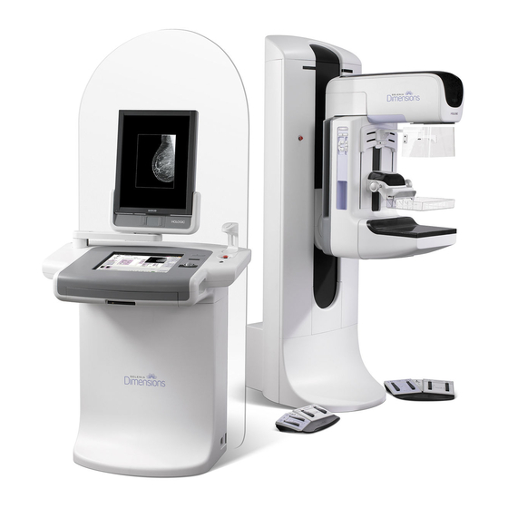
Hologic selenia dimensions Instructions For Use Manual (146 pages)
Digital Mammography System
Brand:
Hologic
| Category:
Medical Equipment
| Size: 11 MB
Table of Contents
Technical Support
3
Table of Contents
5
Preface
15
Intended Uses
15
Indications for Use
16
Contraindications
16
Potential Adverse Effects
16
Product Complaints
16
Summary of Clinical Studies
16
Quality Control
16
User Training
16
Skills Needed for System Use
16
Terms and Definitions
17
Warnings, Cautions, and Notes
19
International Symbols
19
Table P-1: International Symbols
19
How to Use this Document
20
Chapter 1 - General Information
21
Warnings and Precautions
21
Radiation Safety
25
Exposure Duration
25
Operator Radiation Shield
25
Patient Face Shield
25
Exam Room Door Indicators
25
Mechanical Safety
25
Emergency off Switches
25
Table 1-1: Factors that Limit Exposure Duration
25
Chapter 1 - General Information Interlocks
26
Interlocks
26
Compliance
26
Compliance Requirements
26
Compliance Statements
27
Chapter 1 - General Information Compliance
27
Chapter 1 - General Information Label Locations
28
Label Locations
28
Figure 1-1: Selenia Label Locations
28
Figure 1-2: Selenia Value Console Label Locations
29
Chapter 2 - System Components and Controls
31
System Description
31
Film Printer
31
Figure 2-1: Selenia System Description
31
Chapter 2 - System Components and Controls System Power Controls
32
System Power Controls
32
Input Power Circuit Breakers
32
Figure 2-2: Gantry Circuit Breaker
32
Figure 2-3: Acquisition Workstation Circuit Breaker
32
Emergency off Switches
33
Figure 2-4: Emergency off Switch
33
Figure 2-5: Acquisition Workstation Emergency off Switch
33
Figure 2-6: Gantry Emergency off Switches
33
Figure 2-7: Value Console Emergency off Switch
33
Chapter 2 - System Components and Controls Acquisition Workstation Controls and Display
34
Acquisition Workstation Controls and Display
34
Acquisition Workstation
34
Figure 2-8: the Acquisition Workstation Controls
34
Figure 2-9: the Selenia Value Console Controls
34
Keypads
35
Keyboard and Trackball or Mouse
35
Figure 2-10: Keypad Controls
35
Figure 2-11: Selenia Keyboard
35
Keyboard and Screen Controls
36
Bar Code Scanner
36
Figure 2-12: Selenia Function Keys on the Keyboard
36
Table 2-1: Selenia Function Keys
36
The Selenia Display
37
Figure 2-13: Totoku Display
37
Figure 2-14: Barco Display
37
Chapter 2 - System Components and Controls Techmate Controls and Displays
38
Techmate Controls and Displays
38
Figure 2-15: Techmate Controls and Indicators
38
Tubestand Controls and Displays
39
Gantry Controls and Displays
39
Figure 2-16: Tubestand
39
Figure 2-17: Gantry Controls
39
Chapter 2 - System Components and Controls Tubestand Controls and Displays
40
C-Arm Controls and Displays
40
Dual Function Footswitches
41
Figure 2-18: Compression Device
41
Figure 2-19: the Dual Function Footswitch
41
Chapter 3 - Startup, Functional Tests, and Shutdown
43
Procedure for Startup
43
Figure 3-1: Emergency off Switch
43
Figure 3-2: Gantry Circuit Breakers
43
Figure 3-3: Acquisition Workstation Circuit Breaker
43
Figure 3-4: Power on Buttons
43
Table 3-1: System Startup Procedures
43
Chapter 3 - Startup, Functional Tests, and Shutdown Procedure for Startup
44
Controls and Functional Tests
45
Table 3-2: Monthly Control Function Tests
45
Chapter 3 - Startup, Functional Tests, and Shutdown Controls and Functional Tests
46
Monthly System Tests
49
How to Restart the System
49
Restart from Sleep Mode
49
Restart after the Emergency off Switch was Activated
49
Chapter 3 - Startup, Functional Tests, and Shutdown Monthly System Tests
49
Figure 3-5: Operating System Login Screen
49
Chapter 3 - Startup, Functional Tests, and Shutdown How to Restart the System
50
How to Turn on or Reset the Uninterruptible Power Supply (UPS)
50
Figure 3-6: the Acquisition Workstation UPS Switch Lever
50
How to Turn off the UPS
50
Figure 3-7: Value Console UPS Switch
50
UPS Operation for Techmate
51
Figure 3-8: Reset the Techmate UPS
51
Chapter 3 - Startup, Functional Tests, and Shutdown How to Log out
52
How to Log out
52
Figure 3-9: the Sign out Button
52
How to Shut down the System
52
Table 3-3: the Log out Methods
52
Figure 3-10: Exit from Acquisition Workstation Dialog Box
52
Chapter 4 - the Selenia Accessories
53
Introduction
53
Table 4-1: Available Accessories
53
Chapter 4 - the Selenia Accessories Patient Face Shield
54
Patient Face Shield
54
How to Install the Face Shield on the Tubehead
54
How to Remove the Face Shield
54
Figure 4-1: Installation of the Face Shield
54
Compression Paddles
55
How to Install the Compression Paddles
55
How to Remove a Compression Paddle
55
Figure 4-2: Mount the Compression Paddle
55
Maintenance and Cleaning
55
Chapter 4 - the Selenia Accessories Compression Paddles
55
Smart Paddle System
56
FAST Paddle Use
56
Figure 4-3: Shifting Compression Paddle
56
How to Realign the Paddle Front Edge
57
Figure 4-4: Alignment of the Paddle
57
Figure 4-5: Alignment of Adjustment Screws
57
Identification of Compression Paddles
58
Chapter 4 - the Selenia Accessories Magnification Platform
60
Magnification Platform
60
How to Install the Magnification Platform
60
How to Remove the Magnification Platform
60
Figure 4-6: Magnification Platform Installation
60
The Localization Crosshair Device
61
How to Install the Crosshair Device
61
Figure 4-7: Installation of the Crosshair Device
61
How to Remove the Crosshair Device
61
Chapter 4 - the Selenia Accessories the Localization Crosshair Device
61
Figure 4-8: Crosshair Locking Levers
61
Localization Crosshair Device to the Localization Paddle Alignment
62
The Magnification Crosshair Device
62
Figure 4-9: Adjustment Lock Screw
62
Figure 4-10: Installation of the Magnification Crosshair Device
62
Chapter 5 - the User Interface
63
The Three Main User Interface Screens
63
Chapter 5 - the User Interface a Screening Exam Sequence Suggestion
64
A Screening Exam Sequence Suggestion
64
Table 5-1: Workflow Suggestions to Select a Patient and Acquire an Image
64
Chapter 6 - the Select a Patient Screen
67
Introduction
67
Figure 6-1: the Select a Patient Screen
67
Table 6-1: Legend for Figure 6-1
67
Select a Patient
68
How to Query the Modality Worklist Provider
68
How to Search the Acquisition Workstation Database (Local Exams)
68
More Information about Searches
68
How to Add a New Patient
69
Figure 6-2: New Patient Entry Form
69
Chapter 6 - the Select a Patient Screen How to Add a New Patient
69
How to Edit the Existing Patient Data
70
About Patient Information Edits with a Modality Worklist and PACS
70
How to Change the Patient Information after an Image Is Accepted
70
Figure 6-3: the Edit Patient Dialog Box
70
New, Edit, Add a Procedure
71
How to Add a New Procedure
71
Figure 6-4: New Procedure, Edit a Procedure, and Add a Procedure Buttons
71
Chapter 6 - the Select a Patient Screen New, Edit, Add a Procedure
71
How to Edit a Procedure
72
How to Add a Procedure
72
Figure 6-5: New Procedure Dialog Box
72
Figure 6-6: Add a New Procedure Dialog Box
72
Image Output
73
Chapter 6 - the Select a Patient Screen
73
Figure 6-7: Select the Output
73
Chapter 6 - the Select a Patient Screen Exposure Information
74
Exposure Information
74
The Exposure Pane
74
Figure 6-8: Exposure Techniques
74
About Exposure Modes
75
Table 6-2: Exposure Modes
75
Figure 6-9: Breast Density Options
76
Figure 6-10: Accept TEC Exposure Techniques
76
Figure 6-11: the Override Mode
77
Figure 6-12: AEC Exposure and Sensor Position Adjustment On-Screen Settings
78
Table 6-3: AEC Alarm Messages
78
Menu Bar
79
Table 6-4: Menu Bar Options and Functions
79
Chapter 6 - the Select a Patient Screen Menu Bar
80
Edit Menu Function
80
Figure 6-13: the Setup Screen
80
Figure 6-14: View Order Editor
81
Figure 6-15: the Edit Users Dialog Box
82
Table 6-5: User Setup Options
82
Figure 6-16: Edit Output Device Dialog Box
83
Admin Menu
85
Figure 6-17: Choose a New Patient Dialog Box
85
Figure 6-18: Image Management Resend Options
86
Figure 6-19: Manage Queues
88
Table 6-6: How to Use Manage Queues
88
Figure 6-20: Test Pattern Dialog Box
91
Chapter 6 - the Select a Patient Screen Special Modes Buttons
92
Info Menu
92
Special Modes Buttons
92
Non-Imaging Mode Button
92
The Review Button
92
Figure 6-21: Non-Imaging Mode Button
92
The Simulate Capture Button
93
10.0 Generator Status
93
11.0 System Messages
93
12.0 Alarms
93
Chapter 6 - the Select a Patient Screen Generator Status
93
Figure 6-22: the Alarm Icon
93
Chapter 6 - the Select a Patient Screen Alarms
94
Chapter 7 - the Patient Views Screen
95
Figure 7-1: Patient View Screen
95
Table 7-1: Actions on the Patient Views Screen
95
The Patient Views Screen Work with Views
96
Figure 7-2: Buttons Used on the View Screen
96
Table 7-2: View Options
96
Acquire Images
97
Figure 7-3: Ready for Exposure Indicators
97
Chapter 7 - the Patient Views Screen Acquire Images
98
Chapter 8 - the Preview Image Screen
99
Introduction
99
The Preview Image
99
Progressive Preview
99
Figure 8-1: the Preview Image Screen
99
Chapter 8 - the Preview Image Screen the Preview Image
100
Film Label Area
100
Hanging Options
100
Figure 8-2: Hanging Options
100
Tools for Image Enhancement and Annotation
101
Figure 8-3: the Preview Screen Tools
101
Chapter 8 - the Preview Image Screen Tools for Image Enhancement and Annotation
102
Comments
102
Figure 8-4: Image Comments
102
The Edit View Button and Markers
103
Figure 8-5: the Markers in the Preview Pane
103
Implant Present
104
Quick Zoom/Pan
104
Full Zoom/Pan
104
Figure 8-6: Full Zoom/Pan Image
104
Roi
105
Figure 8-7: ROI Size Drop-Down Menu
105
Crosshairs
106
Figure 8-8: Preview with Crosshairs
106
Measurement
107
Figure 8-9: a Measurement on the Preview Screen
107
Magnification
108
Figure 8-10: Preview with Magnification
108
Window/Level
109
Figure 8-11: the Window/Level Settings
109
Display AEC Regions
110
Figure 8-12: AEC Regions
110
Exposure Index
111
Exposure and Dose/Entrance Surface Exposure Information
111
Accept or Reject
111
Accept
111
Figure 8-13: Exposure Information
111
Figure 8-14: Exposure Information
111
Reject
112
Figure 8-15: the Reject Reasons List
112
Figure 8-16: a Rejected Image
112
Additional Information about Accepted/Rejected Images
113
The Image Repetition Information Dialog Box
113
How to Accept a Rejected Image
113
Figure 8-17: Set Accepted Button on Review Screen
113
Figure 8-18: Accept Rejected Image
113
How to Reject an Accepted Image
114
Figure 8-19: Set Rejected Button
114
Chapter 9 - Maintenance and Cleaning
115
General Information
115
For General Cleaning
115
To Prevent Possible Injury or Equipment Damage
115
Chapter 9 - Maintenance and Cleaning Care and Cleaning-Acquisition Workstation and Value Console
116
Care and Cleaning-Acquisition Workstation and Value Console
116
Display
116
Keyboard and Trackball or Mouse
116
Preventive Maintenance
117
Table 9-1: User Preventive Maintenance
117
Chapter 9 - Maintenance and Cleaning Preventive Maintenance
117
Appendix A-System Specifications
119
Dimensional Information
119
Tubestand (Gantry with C-Arm)
119
Acquisition Workstation
119
Figure A-1: Tubestand Dimensions
119
Figure A-2: Acquisition Workstation Dimensions
119
Acquisition Workstation with Dual Swivel Arms
120
Selenia Value Console
120
Figure A-3: Acquisition Workstation with Dual Swivel Arms
120
Figure A-4: Value Console Dimensions
120
Operating Environment
121
Advertisement
Hologic selenia dimensions User Manual (168 pages)
Digital Mammography System, Digital Tomosynthesis System
Brand:
Hologic
| Category:
Medical Equipment
| Size: 20 MB
Table of Contents
Table of Contents
5
List of Figures
11
List of Tables
15
1: Introduction
17
Intended Use
17
Potential Adverse Effects of Mammography Systems on Health
17
Contraindications
18
Intended Use for the User Guide
18
More Information about Tomosynthesis
18
System Capabilities
18
About C-View
20
C-View Software
20
C-View Theory of Operation
20
Warnings
20
Product Complaints
21
Technical Support
21
Warranty Statement
21
1.14.1 Mammography Technologist
22
1.14.2 Radiologist
22
1.14.3 Medical Physicist
22
Hologic Cybersecurity Statement
22
Quality Control Requirements
22
User Profiles
22
Where to Find the Installation Instructions
22
Terms and Definitions
23
Training Requirements
23
Symbols
24
Descriptions of Warnings, Cautions, and Notes
26
Document Conventions
26
2: General Information
27
Figure 1: Selenia ® Dimensions ® System Tubestand
27
System Description
27
Tubestand
27
Acquisition Workstation
28
Figure 2: Acquisition Workstation
28
Safety Information
29
Warnings and Precautions
29
Emergency off Switches
33
Interlocks
33
Compliance
34
Compliance Requirements
34
Compliance Statements
35
Figure 3: Label Locations
37
Label Locations
37
Table 1: List of Labels
38
3: System Controls and Indicators
41
Figure 4: System Power Controls
41
System Power Controls
41
Acquisition Workstation Controls and Indicators
42
Figure 5: Universal Acquisition Workstation Controls and Displays
42
Universal Acquisition Workstation Controls and Displays
42
Figure 6: Premium Acquisition Workstation Controls and Displays
43
Premium Acquisition Workstation Controls and Displays
43
Figure 7: Standard Acquisition Workstation Controls and Displays
44
Standard Acquisition Workstation Controls and Displays
44
Bar Code Scanner
45
Keyboard
45
Premium Acquisition Workstation Touchscreen Display
45
Preview Display
45
Standard Acquisition Workstation Display
45
Universal Acquisition Workstation Display
45
Figure 8: Tubestand Controls and Indicators
46
Tubestand Controls and Indicators
46
C-Arm Controls
47
Compression Device Controls and Displays
47
Figure 10: Compression Device
47
Figure 11: Compression Display
47
Figure 9: C-Arm Controls
47
Dual Function Footswitches
48
Figure 12: Tubehead Display
48
Figure 13: Dual Function Footswitches
48
Tubehead Display
48
Figure 14: Reset the Emergency off Switches
49
Figure 15: Universal Acquisition Workstation Power Buttons
49
Figure 16: Premium Acquisition Workstation Power Buttons
49
Figure 17: Standard Acquisition Workstation Power Buttons
49
How to Turn on the Selenia Dimensions System
49
Preparation
49
Startup
49
Figure 18: Startup Screen
50
Figure 19: Log in Screen
51
Log in
51
Figure 20: C-Arm Controls (Left Side Shown)
52
How to Change the Language
52
Perform the Functional Tests
52
Compression Functional Tests
53
Table 2: Compression Tests
53
C-Arm Movement Functional Tests
54
Table 3: C-Arm up and down Movement
54
Table 4: C-Arm Counterclockwise Rotation
56
Table 5: C-Arm Clockwise Rotation
56
Table 6: C-Arm Rotation Switch
57
Table 7: Automatic C-Arm Counterclockwise Rotation
58
Table 10: C-Arm Collimation
59
Table 8: Automatic C-Arm Clockwise Rotation
59
Table 9: Automatic C-Arm Movement to Zero Position
59
Emergency off Switches Functionality
60
Figure 21: Emergency off Switch Functionality
60
Table 11: Shifting Paddle
60
Figure 22: Universal Acquisition Workstation Power Buttons
61
Figure 23: Premium Acquisition Workstation Power Buttons
61
Figure 24: Standard Acquisition Workstation Power Buttons
61
How to Remove All Power from the Acquisition Workstation
61
How to Turn off the System
61
4: the User Interface
63
Figure 25: an Example Select Function to Perform Screen
63
Select the Function to Perform
63
About the Taskbar
64
Figure 26: the Taskbar
64
Table 12: Taskbar Menus
64
Figure 27: an Example Quality Control Screen
67
How to Perform the Quality Control Tasks
67
Figure 28: the Select Patient Screen
68
Figure 29: the Enterprise Tab
68
Table 13: the Select Patient Screen
68
The Select Patient Screen
68
About the Notices Tab
69
How to Open a Patient
69
4.4.2.1 How to Add a New Patient
70
Figure 30: How to Add a New Patient
70
How to Delete a Patient Manually
70
How to Edit the Patient Information
70
Figure 31: the Filter Tab in the Patient Filter Screen
71
The Patient Filter Screen
71
How to Query the Worklist
72
How to Refresh the Worklist
72
Table 14: the Filter Tab Options (Require Access Privileges)
72
4.4.10 Advanced Workflow Manager
73
About the Admin Button
73
Figure 32: the Generator Tab in an Example Procedure Screen
73
How to Log out
73
The Procedure Screen
73
How to Set the Exposure Parameters
74
Figure 33: Paddle Shift Buttons
75
How to Use the Implant Present Button
75
How to Use the Paddle Shift Feature
75
Figure 34: Exposure in Progress
76
How to Acquire an Image
76
Figure 35: Exposure Complete
77
Figure 36: the Add View Screen
78
How to Add or Remove a View
78
Figure 37: the Procedure Info Window
79
Procedure Information Dialog Box
79
Figure 38: Add Procedure Dialog Box
80
How to Add a Procedure
80
Table 15: Procedure Groups
80
Figure 39: the Edit View Screen
81
How to Edit a View
81
How to Access Image Review Features
82
How to Close a Procedure
82
Figure 40: I-View 2D Contrast Screen
83
How to Use I-View 2D Contrast
83
Figure 41: I-View 2D Contrast Screen, Waiting Period
84
Figure 42: I-View 2D Contrast Screen, Optimal Imaging Period
85
How to Define Contrast Settings
86
How to Add or Edit an Output Group
88
How to Select an Output Group
88
How to Use the Output Groups
88
How to Archive
89
How to Use the Custom Output
89
How to Use the On-Demand Outputs
89
How to Export
90
How to Print
91
5: the Images
93
Introduction
93
Conventional Imaging Sequence of Events
94
Tomosynthesis Imaging Sequence of Events (Tomosynthesis Option)
94
About Auto-Hanging and Auto-Pairing
95
How to Review the Images
96
The Image Review Tools Tab
97
The Notices Tab
98
Other Image Review Tools
99
How to Correct and Reprocess Implant Images
100
Slice Indicator
100
Send the Images to the Output Devices
101
6: How to Use the Accessories
103
How to Install Accessories on the C-Arm
103
Introduction
103
How to Install or Remove the Retractable Face Shield
104
The Patient Face Shields
104
How to Use the Retractable Face Shield
105
How to Install or Remove the Conventional Face Shield
106
Compression Paddles
107
Table 16: Available Accessories
107
Contact and Spot Compression Paddles
108
Magnification Paddles
108
Routine Screening Paddles
108
Large Ultrasound Paddle
109
Localization Paddles
109
How to Install or Remove a Compression Paddle
110
Maintenance and Cleaning
110
FAST Compression Mode
111
Paddle Shift
111
How to Install and Remove the Magnification Stand
112
Magnification Stand
112
Crosshair Devices
113
How to Install and Remove the Localization Crosshair Device
113
How to Use the Localization Crosshair Device
114
How to Install and Remove the Magnification Crosshair Device
115
How to Align the Crosshair Device
116
7: Clinical Procedures
117
At the Gantry
117
Preparation
117
Standard Workflow
117
At the Acquisition Workstation
118
Screening Procedure Example
118
How to Acquire the Exposure
119
How to Position the Patient
119
Set the Exposure Techniques
119
How to Accept a Rejected Image
121
How to Accept or Reject a Pended Image
121
How to Automatically Store the Image
121
Procedure for Needle Localization with Tomosynthesis
122
8: Maintenance and Cleaning
125
Cleaning
125
For General Cleaning
125
General Information about Cleaning
125
To Prevent Possible Injury or Equipment Damage
126
Acquisition Workstation
127
About Reclamation
128
Maintenance
128
Preventive Maintenance Schedule
128
Table 17: User Preventive Maintenance
128
9: System Administration Interface
129
How to Use the Admin Screen
129
Table 18: Admin Screen Functions
130
The about Screen
131
How to Use the System Tools
132
Table 19: Radiologic Technologist Manager-System Tools Functions
133
The System Tools for the Radiologic Technologist Manager
133
Remote Access to Image Reports
134
How to Use the Archive Tool
136
Appendix A Specifications
139
Product Measurements
139
Tubestand (Gantry with C-Arm)
139
Acquisition Workstations
140
General Conditions for Operation
144
Operation and Storage Environment
144
Storage Environment
144
Acquisition Workstation
145
C-Arm
145
Electrical Input
145
Radiation Shield
145
Tubestand
145
Tubestand Technical Information
145
Compression
146
Table 20: Maximum Ma Setting as a Function of Kv
147
X-Ray Beam Filtration and Output
147
X-Ray Tube
147
Light Field Indication
148
X-Ray Collimation
148
X-Ray Generator
148
Image Receptor
149
Imaging System Technical Information
149
Appendix B the System Messages and Alert Messages
151
Error Recovery and Troubleshooting
151
Fault Levels
151
System Messages
151
Types of Messages
151
Table 21: System Messages
152
UPS Operation
154
Appendix C Dimensions Mobile
155
Conditions for Safety and Other Precautions
155
General Information
155
Coach Environment
156
Electrical Input
156
Gantry
156
Mobile Specifications
156
Shock and Vibration Limits
156
Acquisition Workstation
157
Prepare the System for Travel
157
Prepare the System for Use
159
Quality Control Tests
160
Selenia Dimensions Controls and Functional Tests
160
Test the System after Travel
160
Table 22: 2D Dose (EUREF)
161
Table 23: BT Dose (EUREF)
161
Table 24: CEDM Dose (EUREF)
161
Hologic selenia dimensions User Manual (104 pages)
Brand:
Hologic
| Category:
Medical Equipment
| Size: 14 MB
Table of Contents
Technical Support
3
Table of Contents
5
List of Figures
9
List of Tables
11
Intended Use
13
Preface
13
Skills Needed for System Use
13
System Capabilities
13
Users
13
Hologic Cybersecurity Statement
14
Quality Control Requirements
14
Training Requirements
14
Warnings, Cautions, and Notes
14
Terms and Definitions
15
10.0 International Symbols
16
11.0 Document Standards
16
Chapter 1-General Information
17
System Description
17
Safety Information
17
General Safety
17
Figure 1-1: Selenia Dimensions
17
Patient Safety
19
Radiation Safety
20
Data Loss
21
Equipment Damage
21
Emergency off Switches
21
Interlocks
22
Compliance
23
Compliance Requirements
23
Compliance Statements
23
Label Locations
24
Figure 1-2: Label Locations
24
Chapter 2-System Controls and Indicators
25
System Power Controls
25
Figure 2-1: System Power Controls
25
Acquisition Workstation Controls and Display
26
Figure 2-2: Acquisition Workstation Controls and Displays
26
Acquisition Workstation Touchscreen Display
27
Bar Code Reader
27
Keyboard
27
Preview Display
27
Tubestand Controls and Indicators
28
Figure 2-3: Tubestand Controls and Indicators
28
C-Arm Controls
29
Compression Device Controls and Displays
29
Figure 2-4: C-Arm Controls
29
Figure 2-5: Compression Device
29
Figure 2-6: Compression Display
29
Dual Function Footswitches
30
Figure 2-7: Tubehead Display
30
Figure 2-8: Dual Function Footswitches
30
Tubehead Display
30
How to Turn on the Selenia Dimensions
31
Preparation
31
Startup
31
Figure 2-9: the Startup Screen
31
Log in
32
Figure 2-10: How to Log in
32
Perform the Functional Tests
33
Figure 2-11: C-Arm Controls (Left Side Shown)
33
Table 2-1: C-Arm Functional Tests
33
How to Turn off the System
39
How to Remove All Power from the Acquisition Workstation
39
Figure 2-12: Power Buttons
39
Chapter 3-The User Interface
41
Select the Function to Perform
41
Figure 3-1: an Example Select Function to Perform Screen
41
How to Perform the Quality Control Tasks
42
Figure 3-2: an Example Gain Calibration Screen
42
How to Select a Patient
43
How to Open a Procedure
43
Figure 3-3: How to Select a Patient
43
How to Add a New Patient
44
How to Edit the Patient Information
44
How to Delete a Patient
44
Figure 3-4: How to Add a New Patient
44
How to Use a Patient Filter
45
How to Refresh the Worklist
45
Figure 3-5: the Filter Tab in the Patient Filter Screen
45
How to Query the Worklist
46
About the Admin Button
46
How to Log out
46
The Procedure Screen
47
How to Set the Exposure Parameters
47
Figure 3-6: an Example Generator Tab in the Procedure Screen
47
How to Use the Implant Present Button
48
How to Acquire an Image
48
How to Add or Remove a View
49
Figure 3-7: the Add View Screen
49
How to Add a Procedure
50
How to Edit a View
50
Figure 3-8: the Add Procedure Dialog Box
50
Figure 3-9: the Edit View Screen
50
How to Close a Procedure
51
How to Access Image Review Features
51
How to Use the Output Sets
51
How to Select an Output Set
51
How to Add or Edit an Output Set
51
How to Use the On-Demand Outputs
52
How to Archive
52
How to Print
53
Figure 3-10: the Print Screen
53
How to Export
54
How to Use the Paddle Shift Feature
54
About the Taskbar
55
Table 3-1: Taskbar Menus
55
Chapter 4-The Images
57
Introduction
57
Conventional Sequence of Events
57
Tomosynthesis Sequence of Events (Tomosynthesis Option)
57
Figure 4-1: the Preview Screen
57
How to Review the Images
58
Figure 4-2: the Tools Tab in the Procedure Screen
58
Figure 4-3: Marked Images in a Procedure
58
Figure 4-4: Image Review Tools
59
The Image Review Tools Tab
59
Figure 4-5: Image Review Tabs
60
Figure 4-6: Icons Available on the Notices Tab
60
Figure 4-7: the Exposure Index
60
Other Image Review Tools
60
How to Correct and Reprocess Implant Images
61
Send the Images to the Output Devices
61
Chapter 5-How To Use the Accessories
63
Introduction
63
How to Install Accessories on the C-Arm
63
Figure 5-1: C-Arm Accessories
63
The Patient Face Shields
64
How to Install or Remove the Conventional Face Shield
64
Figure 5-2: How to Install the Conventional Face Shield
64
How to Install or Remove the Retractable Face Shield
65
Figure 5-3: How to Align the Retractable Face Shield on the C-Arm
65
How to Use the Retractable Face Shield
66
Figure 5-4: Installation
66
Figure 5-5: Operation
66
Compression Paddles
67
Routine Screening Paddles
67
Contact and Spot Compression Paddles
67
Localization Paddles
68
Magnification Paddles
68
How to Install or Remove a Compression Paddle
69
Maintenance and Cleaning
69
Paddle Shift
69
Figure 5-6: How to Install a Compression Paddle
69
Figure 5-7: How to Remove the Compression Paddle
69
FAST Compression Mode
70
Figure 5-8: the FAST Compression Mode Slide
70
Magnification Stand
71
How to Install and Remove the Magnification Stand
71
Figure 5-9: Installation of the Magnification Stand
71
Crosshair Devices
72
How to Install and Remove the Localization Crosshair Device
72
How to Use the Localization Crosshair Device
72
Figure 5-10: How to Attach the Localization Crosshair Device
72
How to Install and Remove the Magnification Crosshair Device
73
How to Align the Crosshair Device
73
Figure 5-11: How to Install and Remove the Magnification Crosshair Device
73
Chapter 6-Clinical Procedures
75
Standard Workflow
75
Example Screening Procedure
76
How to Position the Patient
76
Set the Exposure Techniques
76
Figure 6-1: Screening Example, Conventional Procedure
76
How to Acquire the Exposure
77
How to Automatically Store the Image
77
How to Accept a Rejected Image
77
How to Accept or Reject a Pended Image
77
Chapter 7-Maintenance And Cleaning
79
General Information
79
For General Cleaning
79
To Prevent Possible Injury or Equipment Damage
80
Acquisition Workstation
81
How to Clean the Preview Display
81
How to Clean the Touchscreen Display
81
How to Clean the Keyboard
81
How to Clean the Fingerprint Reader
81
Chapter 8-System Administration Interface
83
How to Use the Admin Screen
83
Figure 8-1: the Admin Screen
84
Table 8-1: Admin Screen Functions
85
How to Use the System Tools
86
The Radiologic Technologist Manager
86
Table 8-2: Radiologic Technologist Manager-Service Tools Functions
87
Advertisement
Hologic selenia dimensions User Manual (152 pages)
Brand:
Hologic
| Category:
Medical Equipment
| Size: 5 MB
Table of Contents
Table of Contents
5
List of Figures
9
List of Tables
11
Chapter 1 Introduction
13
Intended Uses
13
Indications for Use
14
Contraindications
14
Potential Adverse Effects
14
Intended Use for the User Guide
14
Summary of Clinical Studies
14
Product Complaints
14
Technical Support
14
Hologic Cybersecurity Statement
15
Quality Control Requirements
15
Installation Instructions
15
User Profiles
16
Mammography Technologist
16
Radiologist
16
Medical Physicist
16
Training Requirements
16
Terms and Definitions
17
International Symbols
19
Warnings, Cautions, and Notes
20
Chapter 2 General Information
21
Warnings and Precautions
21
Radiation Safety
25
Exposure Duration
25
Operator Radiation Shield
25
Patient Face Shield
25
Exam Room Door Indicators
25
Mechanical Safety
25
Table 1: Factors that Limit Exposure Duration
25
Emergency off Switches
26
Interlocks
26
Compliance
26
Compliance Requirements
26
Compliance Statements
27
Label Locations
29
Figure 1: Selenia Label Locations
29
Figure 2: Value Console Label Locations
29
Table 2: Label Descriptions
30
Chapter 3 System Components and Controls
33
System Description
33
Figure 3: Selenia System Description
33
Film Printer
34
System Power Controls
34
Input Power Circuit Breakers
34
Figure 4: Gantry Circuit Breaker
34
Figure 5: Acquisition Workstation Circuit Breaker
34
Emergency off Switches
35
Figure 6: Emergency off Switch
35
Figure 7: Acquisition Workstation Emergency off Switch
35
Figure 8: Value Console Emergency off Switch
35
Figure 9: Gantry Emergency off Switches
35
Acquisition Workstation Controls and Display
36
Acquisition Workstation
36
Figure 10: the Acquisition Workstation Controls
36
Figure 11: the Selenia Value Console Controls
36
Keypads
37
Keyboard and Trackball or Mouse
37
Figure 12: Keypad Controls
37
Figure 13: Selenia Keyboard
37
Keyboard and Screen Controls
38
Bar Code Scanner
38
Figure 14: Selenia Function Keys on the Keyboard
38
Table 3: Selenia Function Keys
38
The Selenia Display
39
Tubestand Controls and Displays
39
Figure 15: Tubestand
39
Gantry Controls and Displays
40
C-Arm Controls and Displays
40
Figure 16: Gantry Controls
40
Figure 17: Compression Device
41
Dual Function Footswitches
42
Figure 18: the Dual Function Footswitch
42
Chapter 4 Startup, Functional Tests, and Shutdown
43
Procedure for Startup
43
Figure 19: Emergency off Switch
43
Figure 20: Gantry Circuit Breakers
43
Figure 21: Acquisition Workstation Circuit Breaker
43
Table 4: System Startup Procedures
43
Figure 22: Power on Button and LED
44
Controls and Functional Tests
45
Table 5: Monthly Control Function Tests
45
Monthly System Tests
50
How to Restart the System
50
Restart from Sleep Mode
50
Restart after the Emergency off Switch was Activated
50
How to Turn on or Reset the Uninterruptible Power Supply (UPS)
51
How to Turn off the UPS
51
Figure 23: the Acquisition Workstation UPS Switch Lever
51
Figure 24: Value Console UPS Switch
51
How to Log out
52
Figure 25: the Sign out Button
52
Figure 26: Exit from Acquisition Station Dialog Box
52
Table 6: the Log out Methods
52
How to Shut down the System
53
Chapter 5 The Selenia Accessories
55
Patient Face Shield
55
How to Install the Face Shield on the Tubehead
55
How to Remove the Face Shield
55
Figure 27: Installation of the Face Shield
55
Compression Paddles
56
How to Install the Compression Paddles
56
How to Remove a Compression Paddle
56
Maintenance and Cleaning
56
Figure 28: Mount the Compression Paddle
56
Smart Paddle System
57
FAST Paddle Use
57
Figure 29: Shifting Compression Paddle
57
How to Realign the Paddle Front Edge
58
Figure 30: Alignment of the Paddle
58
Figure 31: Alignment of Adjustment Screws
58
Identification of Compression Paddles
59
Magnification Platform
61
How to Install the Magnification Platform
61
How to Remove the Magnification Platform
62
Figure 32: Magnification Platform Installation
62
Figure 33: Installation of the Crosshair Device
63
Figure 34: Crosshair Locking Levers
63
Figure 35: Adjustment Lock Screw
64
Figure 36: Installation of the Magnification Crosshair Device
64
Figure 37: the Select a Patient Screen
66
Figure 38: New Patient Entry Form
68
Figure 39: the Edit Patient Dialog Box
69
Figure 40: New Procedure, Edit a Procedure, and Add a Procedure Buttons
70
Figure 41: New Procedure Dialog Box
70
Table 7: Exposure Modes
74
Table 8: AEC Alarm Messages
78
Table 9: Menu Bar Options and Functions
78
Table 10: User Setup Options
82
Table 11: How to Use Manage Queues
87
Table 12: Actions on the Patient Views Screen
96
Table 13: View Options
96
Table 14: Workflow Suggestions to Select a Patient and Acquire an Image
115
Table 15: User Preventive Maintenance
123
Table 16: Collimation Settings
131
Table 17: LFS Ma Setting as a Function of Kv
132
Table 18: SFS Ma Setting as a Function of Kv
132
Table 19: Ma Factor as a Function of Mas
132
Table 20: Integrity Checklist
144
Hologic selenia dimensions Site Planning & Installation Manual (56 pages)
Digital Mammography System
Brand:
Hologic
| Category:
Medical Equipment
| Size: 4 MB
Table of Contents
Table of Contents
5
List of Figures
7
List of Tables
9
1: Introduction and General Information
11
Introduction
11
System Description
12
Tubestand Overview
12
Figure 1: Tubestand for Selenia ® Dimensions ® System
12
Acquisition Workstation Overview
13
Figure 2: Acquisition Workstations
13
System Location Considerations
14
Safety
15
Isolation Integrity
15
Shielding
15
Remote X-Ray On/Power on Indicators
15
The X-Ray Interlock
16
Compliance
17
Compliance Requirements
17
Compliance Statements
18
Electromagnetic Compatibility
20
Table 1: Electronic Emissions
20
Table 2: Electromagnetic Immunity Part 1
20
Table 3: Electromagnetic Immunity Part 2
22
Table 4: Separation Distances for RF Equipment
23
2: Specifications and Reference Information
25
Product Measurements
25
Tubestand (Gantry with C-Arm)
25
Figure 3: Tubestand (Gantry with C-Arm) Measurements
25
Universal Acquisition Workstation
26
Figure 4: Universal Acquisition Workstation Measurements
26
Premium Acquisition Workstation
27
Figure 5: Premium Acquisition Workstation Measurements
27
Standard Acquisition Workstation
28
Electrical Input
28
Tubestand
28
Figure 6: Standard Acquisition Workstation Measurements
28
Acquisition Workstation
29
Operation and Storage Environment
29
General Conditions for Operation
29
Storage Environment
29
Center of Gravity Reference
30
Figure 7: Gantry Center-Of-Gravity Reference
30
Figure 8: Premium Acquisition Workstation Center-Of-Gravity Reference
31
Figure 9: Standard Acquisition Workstation Center-Of-Gravity Reference
32
Figure 10: Universal Acquisition Workstation Center-Of-Gravity Reference
33
3: Site Planning Checklist
35
Table 5: Room Requirements
36
Table 6: Clearance Requirements
38
Table 7: Power Requirements
40
Table 8: Environmental Requirements
42
Advertisement
Related Products
Hologic SUPERSONIC IMAGINE AIXPLORER MultiWave
Hologic SUROS ATEC Pearl
Hologic SUROS ATEC Sapphire
Hologic SUROS ATEC Emerald
Hologic TruNode S-10
Hologic Sentinelle Medical Vanguard
Hologic SecurView DX
Hologic 3Dimensions
Hologic Acessa ProVu
Hologic Affirm
Hologic Categories
Medical Equipment
Laboratory Equipment
Server
Control Systems
Microscope
More Hologic Manuals
Login
Sign In
OR
Sign in with Facebook
Sign in with Google
Upload manual
Upload from disk
Upload from URL