
Related Manuals for KVM-TEC MASTERflex KT-6012


Summary of Contents for KVM-TEC MASTERflex KT-6012
- Page 1 KT - 6012 MASTERflex Single Copper KT - 6022 MASTERflex Dual Copper MANUAL KT - 6013 Masterflex Single Fiber KT - 6023 Masterflex Dual Fiber www.kvm-tec.com Check out our Installation Channel:...
- Page 2 COMPATIBILITY kvm-tec Extender Compatibility kvm-tec Extender Compatibility remote Remote Easyline Flexline Scalableline Matrixline Ultraline media4Kconnect Gateway2GO Easyline not scalable ECOsmart Flexline only Maxflex is scalable media4Kconnect not scalable media4Kconnect not scalable SPECIAL media4Kconnet not scalable 12G SDI Scalableline Full HD...
-
Page 3: Table Of Contents
2.2.2 Mounting kits (optional) 2.3 Installing the extender 2.4 Quickinstallation MASTERflex single copper 2.5 Quickinstallation MASTERflex dual in copper 2.6 Quickinstallation MASTERflex single in fiber 2.7 Quickinstallation MASTERflex dual in fiber kvm-tec | 3 Misprints, errors and technical changes reserved... - Page 4 3.4.4 Display the last received image „Freeze Last Image“ 3.4.5 USB Emulation Mode 3.4.6 Power redundance Alert and Link redundance Alert 3.4.7 Diagnosis Menu 3.5 DDC Menu 3.5.1 DDC Main (single) 3.5.2 DDC Second (dual) 3.6 Extender Settings 4 | kvm-tec Misprints, errors and technical changes reserved...
- Page 5 3.7.9 Mouse speed 3.7.10 Monitor sync strength 3.8 Update 3.8.1 Firmware update with Switching Manager 3.8.2 Firmware update with USB stick 3.9 Unlock an upgrade 3.9.1 Enable or Disable USB Memory upgrade kvm-tec | 5 Misprints, errors and technical changes reserved...
- Page 6 5. Troubleshooting & First Aid 6.Maintance & Care 6.1 Extender care 6.2. Disposal 7. Warranty 7.1. Standard warranty 7.2 Extended warranty 8. Cable requirements 8.1 Requirements for CAT5e/6/7 cables 8.2 Requirements fiber cables 6 | kvm-tec Misprints, errors and technical changes reserved...
- Page 7 TABLE OF CONTENT 8.2.1 Multi-Mode (standard) 8.2.2 Single-Mode (optional) 9. Requirements network- switch 9.1 Recommended Switches 10. Address & phone / emails 11. Notes kvm-tec | 7 Misprints, errors and technical changes reserved...
-
Page 8: Introduction
1. INTRODUCTION Congratulations on the purchase of your new MASTERflex MV/MV-F KVM Extender. You have bought a high quality extender. These instructions are part of this product. They contain important information regarding safety, use and disposal for every user of the MASTERflex MV and MV-F KVM Extender. -
Page 9: Safety Instructions
Prior to connecting to the mains, make sure your local mains voltage matches the rating indicated on the product. • The product must be connected to a permanent and earthed AC wall socket. kvm-tec | 9 Misprints, errors and technical changes reserved... - Page 10 Wipe the housing with a damp cloth. Electrical/ electronic parts must not be cleaned. • Alterations to the product and technical modifications are not permitted. 10 | kvm-tec Misprints, errors and technical changes reserved...
-
Page 11: Technical Specifications
Anodized aluminium Dimensions: approx. 97,5 x 41 x 103,5 mm / 3.83x 1.57 x 4.7 inch Weight: local unit 302g/0.66lbs. remote unit 291g/0.64lbs Expected product life: 82 820 hours / 9.5 years kvm-tec | 11 Misprints, errors and technical changes reserved... -
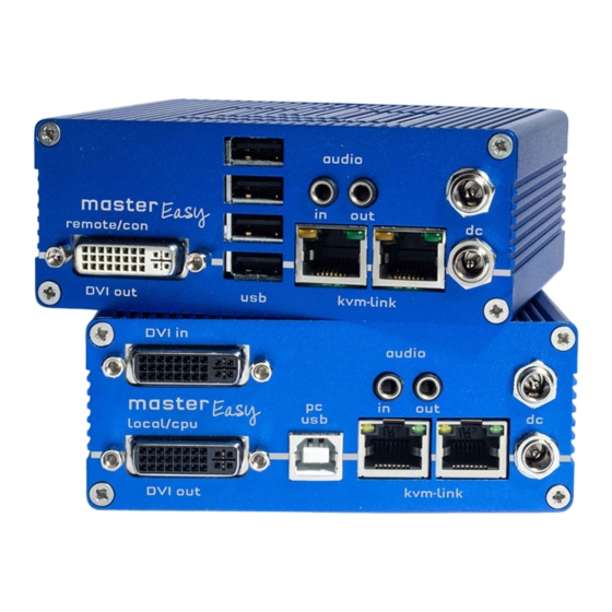
Page 12: About Your Masterflex Single Copper
Audio out to PC kvm-link Networkcable redundant kvm-link Networkcable connection for 12V1A power supply redundant connection 12V2A power supply LED STATUS yellow LINK ok green Video ok green blinking Video and USB activity 12 | kvm-tec Misprints, errors and technical changes reserved... - Page 13 12 V network cable kvm-link connection for CAT5/6/7 cable redundant connection power supply 12V1A redundant connection power supply 12 V2A LED STATUS yellow LINK ok green Video ok green blinking Video and USB activity kvm-tec | 13 Misprints, errors and technical changes reserved...
-
Page 14: About Your Masterflex Dual Copper
Audio Out to PC kvm-link connection network cable kvm-link connection network cablel connection 12V1A power supply connection 12V1A power supply LED STATUS yellow LINK ok green Video ok green blinking Video and USB activity 14 | kvm-tec Misprints, errors and technical changes reserved... - Page 15 12 V networkcable kvm-link connection for CAT5/6/7 cable connection power supply 12V1A connection power supply 12V1A LED STATUS yellow LINK ok green Video ok green blinking Video and USB activity kvm-tec | 15 Misprints, errors and technical changes reserved...
-
Page 16: About Your Masterflex Extender Dual In Fiber
Fibercable redundant kvm-link connection for fibercable connection 12V1A power supply redundant connection 12V1A power supply LED STATUS yellow LINK ok green Video ok green blinking Video and USB activity 16 | kvm-tec Misprints, errors and technical changes reserved... - Page 17 12V1A audio out Audio to loudspeaker audio in Audio in from microphone etc . LED STATUS yellow LINK ok green Video ok green blinking Video and USB activity kvm-tec | 17 Misprints, errors and technical changes reserved...
-
Page 18: Product Elements - Masterflex Extender Single In Fiber
Audio out to PC kvm-link connection fiber cable redundant kvm-link connection fibercable connection power supply 12V1A redundant conenction power supply LED STATUS yellow LINK ok green Video ok green blinking Video and USB activity 18 | kvm-tec Misprints, errors and technical changes reserved... - Page 19 12V1A power supply redundant connection power supply LED STATUS yellow LINK ok green Video ok green blinking Video and USB activity kvm-tec | 19 Misprints, errors and technical changes reserved...
-
Page 20: Product Elements - Masterflex Extender Dual Fiber
Audio to PC kvm-link connection networkcable redundant kvm-link connection networkcable connection power supply 12V1A redundant connection power supply 12V1A LED STATUS yellow LINK ok green Video ok green blinking Video and USB activity 20 | kvm-tec Misprints, errors and technical changes reserved... - Page 21 12V1A redundant connection power supply 12V1A LED STATUS yellow LINK ok green Video ok green blinking Video and USB activity kvm-tec | 21 Misprints, errors and technical changes reserved...
-
Page 22: About Your Masterflex Backpanel
1. INTRODUCTION 1.9 ABOUT YOUR MASTERFLEX BACKPANEL BACKSIDE SMARTflex Single & SMARTflex Dual Name Function LED Status display LED Status Reset Button for Reset 22 | kvm-tec Misprints, errors and technical changes reserved... -
Page 23: About The Status Led
Anzeige des Lichtes Bedeutung shining only network connection available fast flashing No active connection shining No video signal shining everything works A detailed error description can be found in chapter First Aid kvm-tec | 23 Misprints, errors and technical changes reserved... -
Page 24: Installation Of The Extender
2 x Audio cable 1,8m/5.9ft (opt) delivery content - Remote (CON) 1 x MV2 remote (CON) 1 x wall power supply 12V 1A (EU-plug or int plug) 4 x rubber feet 24 | kvm-tec kvm-tec | 24 Misprints, errors and technical changes reserved... - Page 25 (alternativ Single-Mode up to 20km/12mi ItemNr 6835 ) 4 x rubber feet Delivery content Remote (CON) 1 x MV2 remote (CON) 1 x wall power supply 12V 1A (EU-plug or INT plug) 4 x rubber feet kvm-tec | 25 Misprints, errors and technical changes reserved...
-
Page 26: Mounting Options
Rack mounting kit RMK- FLEX- FN - T Part-Nr. KT - 6233 RMK- FLEX-FN The rack mounting kit RMK-FN is for assembling kvm-tec MASTERflex extenders. - 4 single or 4 dual Extender. It consists of 19“ Rack Shelf, an alu-faceplate and a power supply. -
Page 27: Installing The Extender
In the case of the latter, an additional Network Switch must be installed. With a Network Switch, each user can gain quick access to any of the required computers. point to point connection & Matrix Switching System kvm-tec | 27 Misprints, errors and technical changes reserved... -
Page 28: Quickinstallation Masterflex Single Copper
Using a switch: Connect all endpoints to the switch. Ensure that all connections have a bandwith of 1Gbit/sec. For video sharing the network has to support IGMP snooping. 28 | kvm-tec Misprints, errors and technical changes reserved... -
Page 29: Quickinstallation Masterflex Dual In Copper
Using a switch: Connect all endpoints to the switch. Ensure that all connections have a bandwith of 1Gbit/sec. For video sharing the network has to support IGMP snooping. kvm-tec | 29 Misprints, errors and technical changes reserved... -
Page 30: Quickinstallation Masterflex Single In Fiber
1Gbit/sec. For video sharing the network has to support IGMP snooping. Almost done! Connect the audio cable Local audio/out to the PC audio/in and Remote audio/out with the audio cable to the microphone 30 | kvm-tec Misprints, errors and technical changes reserved... -
Page 31: Quickinstallation Masterflex Dual In Fiber
Using a switch: Connect all endpoints to the switch. Ensure that all connections have a bandwith of 1Gbit/sec. For video sharing the network has to support IGMP snooping. kvm-tec | 31 Misprints, errors and technical changes reserved... -
Page 32: Start Up
2. Pull the metal latch of the SFP module forwards until it is at a right angle. 3. Replace the SFP module with the other module. Put the metal latch back in position. Only use SFP modules from kvm-tec, or recommended by kvm-tec. 32 | kvm-tec... -
Page 33: Removing A Catx Cable
Press the latch down and slowly pull the cable out. 2.11 REMOVING A FIBER CABLE To remove a fiber cable: • Press the latch down and slowly pull the cable out. kvm-tec | 33 Misprints, errors and technical changes reserved... -
Page 34: Best Practice For Windows 10
2. INSTALLATION OF THE EXTENDER 2.12 BEST PRACTICE FOR WINDOWS 10 Disable USB Energy Savings in Windows 10 34 | kvm-tec Misprints, errors and technical changes reserved... - Page 35 2. INSTALLATION OF THE EXTENDER kvm-tec | 35 Misprints, errors and technical changes reserved...
- Page 36 2. INSTALLATION OF THE EXTENDER 36 | kvm-tec Misprints, errors and technical changes reserved...
-
Page 37: Extender Settings
DDC Option Fixed Setting 1020 x 1080 Local Settings Settings Local Remote Setting Settings Remote U Update Flash FW Update firmware About Overview Upgrade overview Link redundancy for single units Q Exit Finish kvm-tec | 37 Misprints, errors and technical changes reserved... -
Page 38: System Status
Link status shows whether there is a physical connection available. Connected indicates if kvm data is currently able to be transmitted. Video and USB show if data is currently being transmitted. 38 | kvm-tec Misprints, errors and technical changes reserved... -
Page 39: Viewing The Current Firmware Version
Freeze last Image (Disabled)Disabled/Enabled USB Emulation Mode (Disabled ) Disabled/Enabled USB Save Feature (mass storage usable) Disabled/Enabled Diagnosis Diagnostic menu Unlock Features Activate features IP Management IP Management Link redundancy for single units kvm-tec | 39 Misprints, errors and technical changes reserved... -
Page 40: Point To Point
By pressing the „M“ button you can switch the Matrix Switching Mode off and on 3.4.3 USB SAVE FEATURE The kvm-tec feature „USB save“ prevents the intrusion of viruses via the USB interface by deacti- vating mass storage devices. By pressing the key „S“ you can switch the USB save feature on and off... -
Page 41: Display The Last Received Image „Freeze Last Image
Press the D button to enable or disable the function. Press ESC to return to the main menu. Press I to enable or disable the function. Press ESC to return to the main menu kvm-tec | 41 Misprints, errors and technical changes reserved... -
Page 42: Usb Emulation Mode
Link Redundance Alert (Only for single devices with two RJ45 jacks): „PRIM LINK LOST“ / „SEC LINK LOST“ / „BOTH LINK LOST“ Oder „SEC LINK ERROR“ with active redundancy „PRIM LINK ERROR“ with active redundancy. 42 | kvm-tec Misprints, errors and technical changes reserved... -
Page 43: Diagnosis Menu
In the Diagnosis menu, the runtimes of the individual connected channels are displayed. Both Remote Unit and Partner Local Unit are listed. Additionally you get the CPU temperature information of both units. Another feature is the cable test kvm-tec | 43 Misprints, errors and technical changes reserved... - Page 44 The test can be ended at any time by pressing the “Enter” or “→” key. If no error has occurred, the status reports: “Test OK! If errors occurred during the test, the status displays the sum of all errors that occurred. 44 | kvm-tec Misprints, errors and technical changes reserved...
-
Page 45: Ddc Menu
Extender - Press the keys 4 to 8 to use a predefined resolution, which is saved. 3. press ESC to return to the main menu kvm-tec | 45 Misprints, errors and technical changes reserved... -
Page 46: Ddc Main (Single)
3. EXTENDER SETTINGS 3.5.1 DDC MAIN (SINGLE) 46 | kvm-tec Misprints, errors and technical changes reserved... -
Page 47: Ddc Second (Dual)
3. EXTENDER SETTINGS 3.5.2 DDC SECOND (DUAL) kvm-tec | 47 Misprints, errors and technical changes reserved... -
Page 48: Extender Settings
Display the Extender Settings menu: 1.Make sure that the main menu is open. 2.Press the L button. The Local Settings menu is displayed. 3.Press the R button. The Remote Settings menu is displayed 48 | kvm-tec Misprints, errors and technical changes reserved... -
Page 49: Local Settings
View the local or remote Extender settings: - Press the L button to display the Local Setting menu. USB Compatibility Mode Disabled/Enabled USB Remote Wakeup Disabled/Enabled Compatibility with Linux Disabled/Enabled Bandwidth Reduction VGA Parameters VGA-1 Parameters kvm-tec | 49 Misprints, errors and technical changes reserved... -
Page 50: Usb Compatibility Mode
To enable / disable the USB compatibility mode 1. From the Extender Settings menu, press the L key: The LOCAL SETTINGS menu appears 2. Press the U key to enable or disable the USB compatibility mode 50 | kvm-tec Misprints, errors and technical changes reserved... -
Page 51: Usb Remote Wake Up
3. EXTENDER SETTINGS 3.6.3. USB REMOTE WAKE UP The PC can be set into sleep mode and can be reactivated with any key. kvm-tec | 51 Misprints, errors and technical changes reserved... -
Page 52: Compatibility With Linux
In this case please activate the Linux compatibility mode 3.6.5 BANDWIDTH REDUCTION Here the bandwidth can be reduced. The basic setting is 0! You can change the bandwidth with +/- or u/d. 52 | kvm-tec Misprints, errors and technical changes reserved... -
Page 53: Vga Parameters
- Press I to reset the parameters to the default values. - Press S to save the settings and exit the menu. - Press Q to exit without saving. VGA Parameters kvm-tec | 53 Misprints, errors and technical changes reserved... -
Page 54: Remote Settings
3. EXTENDER SETTINGS VGA-1 Parameters 3.7 REMOTE SETTINGS • Press the R button to display the Remote Setting menu. 54 | kvm-tec Misprints, errors and technical changes reserved... -
Page 55: Editing A Keyboard Layout
2. Press the K key. The Keyboard Locale menu opens: • Press E to select English (EN) • Press D to select German (DE) • Press F to select French (FR) kvm-tec | 55 Misprints, errors and technical changes reserved... -
Page 56: Editing Keyboard Shortcuts
3. Use the arrows to select a command. 4. Press E to edit the shortcut. To edit: Press a single key. Edit the frequency with left and right arrows. OR - Press a key combination dual single 56 | kvm-tec Misprints, errors and technical changes reserved... -
Page 57: Setting The Audio Volume
From the Extender Settings menu, press the R key. The Remote Settings menu appears. Press the A key. The Audio Input Gain menu appears. Press arrow left / right to change volume Press arrow up / down to set direction kvm-tec | 57 Misprints, errors and technical changes reserved... -
Page 58: Usb Share Any Key
By pressing the button „B“ the USB Share any Key mode can be activated or deactivated. If the USB share any key, the USB function can be taken over with any key. If the function is deactivated, this works with the predefined hotkeys (see 3.7.2.) 58 | kvm-tec Misprints, errors and technical changes reserved... -
Page 59: Using The Power Saving Mode
To reactivate the monitor, press any key on the keyboard or connect to a partner. Enable and disable power save mode on the remote screen. In the main menu, press G > R. kvm-tec | 59 Misprints, errors and technical changes reserved... -
Page 60: Hiding System Status Menu
3. EXTENDER SETTINGS 3.7.6 HIDING SYSTEM STATUS MENU Press N in the Remote Settings menu. This will remove the status screen and the image remains black. 60 | kvm-tec Misprints, errors and technical changes reserved... -
Page 61: Change Keyboard Fallback Modus
To use the OSD menu, the keyboard on the remote device must be identified. For most keyboards, use the 0 setting. When using USB, some mice act like a keyboard. In this case, select fallback mode 1 or 2. kvm-tec | 61 Misprints, errors and technical changes reserved... -
Page 62: Lock Menu
3. EXTENDER SETTINGS 3.7.8 LOCK MENU This menu protects the OSD control and after 5 minutes the OSD can no longer be activated. 62 | kvm-tec Misprints, errors and technical changes reserved... -
Page 63: Mouse Speed
Some monitors are very sensible regarding frequency changes. Therefore the changes should be done slow and the synchronization takes a bit more time The monitor sync strength can be adjusted between 0-3. kvm-tec | 63 Misprints, errors and technical changes reserved... - Page 64 3. EXTENDER SETTINGS single dual 64 | kvm-tec Misprints, errors and technical changes reserved...
-
Page 65: Update
It takes about 2 minutes until the firmware is loaded into the extender. The bar on the right in the column the main window fills blue 2. is the update. ATTENTION Only if the bar is grey, the update is finished. kvm-tec | 65 Misprints, errors and technical changes reserved... -
Page 66: Firmware Update With Usb Stick
2. copy the update file (ending in .kvm) to the USB stick 3. make sure that the update file is directly on the stick and that it is not in any subdirectory 4. the USB stick must be formatted with FAT-32 66 | kvm-tec Misprints, errors and technical changes reserved... -
Page 67: Unlock An Upgrade
6. The extender will automatically restart. 7. To confirm the upgrade has been unlocked return to the Options Overview menu and check that the relevant upgrade is now displayed in green kvm-tec | 67 Misprints, errors and technical changes reserved... - Page 68 3. EXTENDER SETTINGS 68 | kvm-tec Misprints, errors and technical changes reserved...
-
Page 69: Enable Or Disable Usb Memory Upgrade
This upgrade enables the use of VGA analog signals on the local unit. For a description on how to enable or disable the sound upgrade, see in Chapter 3.9 “Unlock an upgrade. kvm-tec | 69 Misprints, errors and technical changes reserved... -
Page 70: About This Device
By pressing the „A“ button, or by selecting the arrow keys, you can access the info menu, where you can obtain information about hardware and software versions, as well as the activated upgrades. You can also see the current firmware version here. single dual 70 | kvm-tec Misprints, errors and technical changes reserved... -
Page 71: Network Settings
All network settings, user administration and extender management are done via the included Switching Manager software and all functions are described in the Switching Manager 2000 manual. You can download the manual from our website. www. kvm-tec.com kvm-tec | 71... -
Page 72: Display Switching List
4. NETWORK SETTINGS 4.1 DISPLAY SWITCHING LIST Available devices that the user can connect to are displayed here. Create shortcut: You can create a shortcut with the following key combination „Strg+Alt+Print“ 72 | kvm-tec Misprints, errors and technical changes reserved... -
Page 73: Push / Get List
4. NETWORK SETTINGS 4.2 PUSH / GET LIST Display of all extenders that can be shared. The current image of the workstation can be shared with other remote units via this list kvm-tec | 73 Misprints, errors and technical changes reserved... -
Page 74: Favorite List
4. NETWORK SETTINGS 4.3 FAVORITE LIST A total of 8 favourites can be defined. The connection of these 8 favourites is possible with shortcuts from 1-8 74 | kvm-tec Misprints, errors and technical changes reserved... -
Page 75: Connecting, Disconnecting Or Selecting Acurrent Workplace Connected Devices
If you are not connected through a network switch, you can connect directly to an encoder with point-to-point mode. In the main menu, press P. After logging in, the user receives his personalized lists (Devices, Favorites List). kvm-tec | 75 Misprints, errors and technical changes reserved... -
Page 76: Searchbox-Function
„TAB“ key. Now you can enter a string to search for the Extender you want to see. Press the Return key, you should now see a reduced list of Extenders. 76 | kvm-tec Misprints, errors and technical changes reserved... -
Page 77: Ip Management
4. NETWORK SETTINGS 4.6 IP MANAGEMENT The KVM extenders from kvm-tec support three different addressing methods. The IP Manage- ment menu is only accessible in the active “Matrix Switching Mode” under Features. Default In default mode, each Extender generates an IP address using the ID number to avoid number collisions in the network. - Page 78 4. NETWORK SETTINGS DHCP The KVM extenders from kvm-tec support the DHCP protocol (Dynamic Host Configuration Protocol). This allows the assignment of network addresses by a DHCP server. Static IP In Static-IP mode the IP addresses can be assigned via the OSD. It is necessary to be connected to a local partner to be able to transmit IP addresses.
- Page 79 If all four IP addresses are overwritten, “Save/send settings” must be used to transmit the new values to the extenders. Static IP addresses can only be overwritten in Static IP mode. kvm-tec | 79 Misprints, errors and technical changes reserved...
-
Page 80: Troubleshooting & First Aid
Install current firmware from our homepage www.kvm- green has an incorrect tec.com/support display LED is blinking Different firmware Please contact the kvm-tec support team via e-mail: green or USB is not support@kvm-tec.com or by phone: +43 2253 81912 30 compatible LED light Different firmware... - Page 81 Contact kvm-tec Contact kvm-tec support support We are here for you to answer your questions about installation? Manual download www.kvm-tec.com kvm-tec Installationchannel on our homepage personally +43 2253 81912 kvm-tec | 81 Misprints, errors and technical changes reserved...
-
Page 82: Maintance & Care
6.MAINTANCE & CARE 6.MAINTANCE AND CARE 6.1 EXTENDER CARE Caution! Do not use solvent-containing cleaners. Do not use wipes, alcohols (e.g. spiritus) or chemicals as these could damage the surface. 6.2. DISPOSAL This symbol on the product, the accessories or packaging indicates that this product must not be treated as unsorted municipal waste, but must be collected separately! Dispose of the product via a collection point for the recycling of waste electrical and electronic equipment within the EU and in other European... -
Page 83: Warranty
7. WARRANTY 7.1. STANDARD WARRANTY The warranty period is 24 months from the date of purchase. The warranty expires in case of: • External effort • improper maintenance • Violation of the operating instructions • lightning damage Please, contact us first before returning the product. 7.2 EXTENDED WARRANTY 2 years standard warranty Art Nr KT - 9003 warranty extension to 5 years... -
Page 84: Cable Requirements
The shield should be contiguous and connected to both ends. A shielded patch cable is allowed for connection to the device. Schema EIA/TIA-568 B Color Orange/White Orange Green/White Blue Blue/White Green Brown/White Brown 84 | kvm-tec Misprints, errors and technical changes reserved... -
Page 85: Requirements Fiber Cables
Up to 20 km transmission distance. • Requires dedicated fiber connection: cable type Singlemode with LC connector Wavelength ( ) of 850 nm in multi-mode or 1310 nm TX -1550 nm RX in single-mode kvm-tec | 85 Misprints, errors and technical changes reserved... -
Page 86: Requirements Network- Switch
The network switch must meet the following specifications: 1 Gigabit switch, with a port-to-port transfer rate of 1 Gigabit/second. The following switches have all been tested and verified to work with all kvm-tec extenders. Network requirements Matrix System UDP Version... -
Page 87: Address & Phone / Emails
10. ADDRESS & PHONE / EMAILS 10. ADDRESS & PHONE/EMAIL If you have any questions about our products, please contact kvm-tec or your dealer. kvm-tec electronic gmbh Gewerbepark Mitterfeld 1A 2523 Tattendorf Austria Phone: 0043 (0) 2253 81 912 Fax: 0043 (0) 2253 81 912 99 Email: support@kvm-tec.com... -
Page 88: Notes
11. NOTES 88 | kvm-tec Misprints, errors and technical changes reserved...
Need help?
Do you have a question about the MASTERflex KT-6012 and is the answer not in the manual?
Questions and answers