KVM-TEC USBflex User Manual
Hide thumbs
Also See for USBflex:
- Quick installation (2 pages) ,
- Quick installation (2 pages) ,
- Quick installation (2 pages)
Table of Contents
Advertisement
Quick Links
Advertisement
Table of Contents

Related Manuals for KVM-TEC USBflex


Summary of Contents for KVM-TEC USBflex
- Page 1 Check out our Installation Channel: kvm-tec User manual 6031 SET USBflex single in Kupfer 6031L CPU/LOCAL 6031R CON/REMOTE 6032 SET USBflex single in Fiber 6032L CPU/LOCAL 6032R CON/REMOTE kvm-tec = C connect collaborate communicate control www.kvm-tec.com...
-
Page 2: Table Of Contents
1. Introduction 1.1 Intended Use 1.2 Safety Instructions 1.3 Technical Spezifications 1.4 About the product - USBflex Single copper 1.5 Product elements - USBflex single fiber 1.6 Product elements - USBflex Backside 1.7 About the Status LED 1.8 Unpacking and checking the contents 1.9 Mounting options... -
Page 3: Introduction
9. contacts & phone / emails course of technological progress are reserved. In these user instructions the USBflex Extender is referred to as ‘product’ or ‘extender‘. The USBflex is referred to as the ‘local unit’ CPU and the 10. Notes UB1/Monitor is referred to as the ‘remote unit‘... -
Page 4: Safety Instructions
• Prior to connecting to the mains, make sure your local mains voltage matches the rating indicated on the product. • The product must be connected to a permanent and earthed AC wall socket. 6 | kvm-tec kvm-tec | 7... -
Page 5: Technical Spezifications
1. introduction 1. introduction 1.4 ABoUT ThE ProdUCT - USBFlEx SInglE CoPPEr 1.3 TEChnICAl SPEzIFICATIonS Typ: KVM Extender local/CPU Unit and remote/CON Unit Remote /cON extender Modell: USBflex single copper UB1 KVM Extender USBflex single fiber UB1-F KVM Extender Voltage supply: 100 - 240 V;... -
Page 6: Product Elements - Usbflex Single Fiber
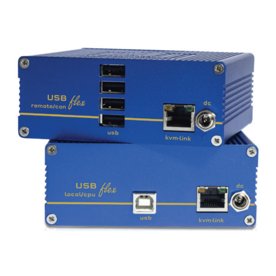
1. introduction 1. introduction 1.5 ProdUCT ElEMEnTS - USBFlEx SInglE FIBEr Remote/cON extender Local /cPU extender name Function name Function USB to PC USB from Videocamera, Photocamera, Joystick kvm-link Connection for CAT5/6/7 cable kvm-link Conenction for CAT5/6/7 cable connection power supply 12V1A... -
Page 7: Product Elements - Usbflex Backside
1. introduction 1. introduction 1.6 ProdUCT ElEMEnTS - USBFlEx BACKSIdE Local /cPU extender name Function LED Status Display the status of the extender Reset Button for reset name Function USB to PC kvm-link Connection for CAT5/6/7 cable Conenction 12V1A power supply... -
Page 8: About The Status Led
Autoupdate Link connection extended Initialisation received command mode USBflex Single copper main Led Update Failed Local/cPU Unit 1 x UB1 local/CPU Slow 1 x wall power supply unit 12 V 1A (EU-plug or Int plug) Orange 1 x USB cable 1,8m/5.9ft... -
Page 9: Mounting Options
The following mounting kits are available: Rackmounting RMK-FLEX-F Part Nr. 6232 RMK-FLEX-F The rack mounting kit RMK-FLEX- F is for mounting kvm-tec USBflex single extenders. It consists of a19“ rack shelf and an alu-faceplate. Rackmounting RMK- FLEX- FN - T Part-Nr. 6233 RMK- FLEX-FN The rack mounting kit RMK-FLEX-FN is for assembling kvm-tec USBflex extenders. -
Page 10: Quickinstallation Usbflex Single Copper
3. Connect the CPU / Local and the CON / Remote Unit with a network cable. HAVE FUN - your kvm-tec Extender is now in use for many years ( MTBF approx 10 years) HAVE FUN - your kvm-tec Extender is now in use for many years ( MTBF approx 10 years) -
Page 11: Start Up
LED lights green. The monitor will displays your computer’s desktop or any open applications. 2.5 rEMoVIng A CATx CABlE To remove a CATx cable: • Press the latch down and slowly pull the cable out. 20 | kvm-tec kvm-tec | 21... - Page 12 2. InSTAllATIon oF ThE ExTEndEr 2. INSTALLATION Of The exTeNder 22 | kvm-tec kvm-tec | 23...
-
Page 13: Configure The Extender
All network settings, user administration and extender management are done via the included Switching Manager software and all functions are described in the Switching Manager 2000 No Power USB is not manual. You can download the manual from our website. www. kvm-tec.com (No LED) working Are the USB... -
Page 14: Maintance & Care
By disposing of the packaging and packaging waste in the proper manner, you help to avoid possible hazards for the environment and public health. Art Nr 9003 warranty extension to 5 years per Set Art Nr 9002 warranty extension to 5 years per Unit 26 | kvm-tec kvm-tec | 27... -
Page 15: Cable Requirements
Only use shielded installation cable with min. cross section of 24 AWG throughout the length. A list of kvm-tec tested and recommended switches can be found on our website at • The shield should be contiguous and connected to both ends. A shielded patch cable is allowed for connection to the device. -
Page 16: Contacts & Phone / Emails
10. NOtes 9. cONtActs & PHONe / emAILs 9. AddRess & PHONe/emAIL If you have any questions about our products, please contact kvm-tec or your dealer. kvm-tec electronic gmbh Gewerbepark Mitterfeld 1A 2523 Tattendorf Austria Phone: 0043 (0) 2253 81 912 Fax: 0043 (0) 2253 81 912 99 Email: support@kvm-tec.com...
Need help?
Do you have a question about the USBflex and is the answer not in the manual?
Questions and answers