Advertisement
Quick Links
Frequency central
5 x 5 active patchbay/matrix mixer/switcher with normal and inverted outputs and attenuators
Looking Glass is an 5x5 active patchbay/matrix mixer/switcher. It features:
•
5 inputs (1 through to 5), each with attenuators
•
5 inverted outputs (A through to E) which are 180
•
5 normal outputs (A through to E) which are in phase with the inputs
•
A switch matrix of 25 push on/push off switches and LED status indicators
Any of the 5 inputs can be patched to any of the 5 outputs simply by pressing the corresponding
switches. A patched signal will appear at both normal and inverted outputs simultaneously.
A single input can be patched to a single output. A single input can be patched to multiple outputs.
Multiple inputs can be patched to a single output. Multiple inputs can be patched to multiple
outputs.
The attenuators allow you to reduce the volume of an incoming signal. If you add many inputs to
one output you will of course cause clipping (which may or may not be desirable!), the attenuators
are your on-board way around this.
Build documentation for:
Looking glass
Main PCB
Control PCB
o
out of phase with the inputs
Advertisement

Subscribe to Our Youtube Channel
Related Manuals for Frequency Central Looking glass


Summary of Contents for Frequency Central Looking glass
- Page 1 Looking glass 5 x 5 active patchbay/matrix mixer/switcher with normal and inverted outputs and attenuators Main PCB Control PCB Looking Glass is an 5x5 active patchbay/matrix mixer/switcher. It features: • 5 inputs (1 through to 5), each with attenuators •...
- Page 2 Control PCB rear – the SMD resistors Looking Glass uses 50 surface mount resistors on the rear of the Control PCB (the 10K are all current limiting resistors for the LEDs, while the 100K are mixing resistors). This may sound intimidating if you haven’t used SMD before, but its quite easy really.
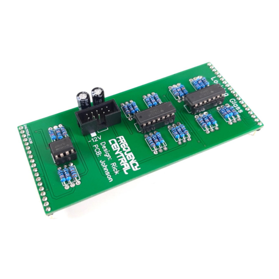
- Page 3 Main PCB front – the through hole components 1. Solder all resistors - don’t mix up the 100R and 100K 2. Solder all IC sockets 3. Solder the power header – if you’re using box type, observe correct polarity 4. Solder all electrolytic capacitors 5.
- Page 4 Make sure that you plug the Main PCB into the Pots ‘n’ sockets PCB the right way around – Frequency Central logo should be the right way up. Hey Eurokidz! Tired of patch cables? Then throw them all away* and use our nifty Looking Glass patchbay/matrix mixer/switcher instead! *Well, not all of them, obviously.
Need help?
Do you have a question about the Looking glass and is the answer not in the manual?
Questions and answers