Advertisement
Frequency central
Build documentation for:
MU system X
Lowpass Filter
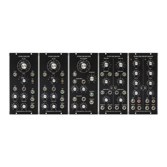
Based on the Roland System 100m VCF with additional 12dB/oct output. MU System X
Lowpass Filter features: Main PCB, Sockets PCB x 7
Key to PCB screen print:
n: This signifies NPN BC547 transistors. Note the correct pinout as shown by the half circles.
p: This signifies PNP BC557 transistors. Note the correct pinout as shown by the half circles.
f: This signifies 2N5485 FETs. Note the correct pinout as shown by the half circles.
The PCB shows the correct orientation for BC547/BC557. Other transistor types can be used
(eg 2N3904/2N3906), but please observe the correct pinout. Please observe the correct
polarity of the electrolytic capacitors.
Advertisement
Table of Contents

Related Manuals for Frequency Central MU System X Lowpass Filter


Summary of Contents for Frequency Central MU System X Lowpass Filter
- Page 1 Frequency central Build documentation for: MU system X Lowpass Filter Based on the Roland System 100m VCF with additional 12dB/oct output. MU System X Lowpass Filter features: Main PCB, Sockets PCB x 7 Key to PCB screen print: n: This signifies NPN BC547 transistors. Note the correct pinout as shown by the half circles.
- Page 2 Bill of Materials 100R x 1 470pF x 4 TL071 x 2 A100K x 2 560R x 8 22uF electrolytic x 8 LM13700 x 2 1K5 x 1 47uF electrolytic x 2 BC547 x 3 B100K x 3 1K8 x 1 BC557 x 1 5K6x 1 10K thermistor x 1...
- Page 3 Main PCB assembly - FRONT Solder all resistors. 2. Solder all IC sockets 3. Solder all non-electrolytic capacitors 4. Solder all transistors and the thermistor 5. Solder the 6 x Alpha pots. Make sure they fit snug to the PCB. Main assembly –...
- Page 4 Socket PCB 1. Solder the 7 sockets to the 7 Socket pcbs, socket sits on it’s silkscreen footprint Final Assembly 1. Present the pcb to the panel, and bolt the two together using the washers and nuts for the pots and switch 2.
Need help?
Do you have a question about the MU System X Lowpass Filter and is the answer not in the manual?
Questions and answers