Advertisement
Frequency central
Build documentation for:
System x filter 2
Based on the Roland System 100m VCF with additional 12dB/oct output
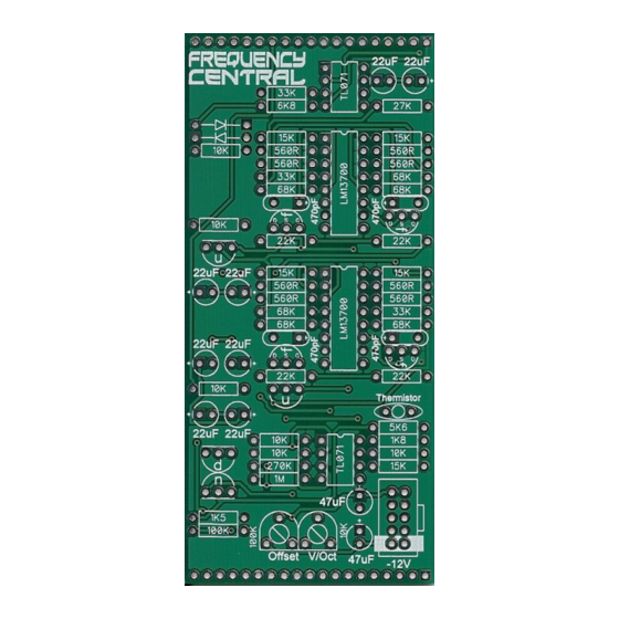
Key to PCB screen print:
n: This signifies NPN BC547 transistors. Note the correct pinout as shown by the half circles.
p: This signifies PNP BC557 transistors. Note the correct pinout as shown by the half circles.
The PCB shows the correct orientation for BC547/BC557. Other transistor types can be used (eg
2N3904/2N3906), but please observe the correct pinout.
Please observe the correct polarity of the electrolytic capacitors.
Advertisement
Table of Contents

Related Manuals for Frequency Central System X Filter 2


Summary of Contents for Frequency Central System X Filter 2
- Page 1 Frequency central Build documentation for: System x filter 2 Based on the Roland System 100m VCF with additional 12dB/oct output Key to PCB screen print: n: This signifies NPN BC547 transistors. Note the correct pinout as shown by the half circles.
- Page 2 Bill of Materials 100R x 1 470pF x 4 TL071 x 2 A100K x 3 560R x 8 22uF electrolytic x 8 LM13700 x 2 these)* 1K5 x 1 47uF electrolytic x 2 BC547 x 3 1K8 x 1 BC557 x 1 B100K x 3 5K6x 1 10K thermistor x 1...
- Page 3 PCB. Main PCB grounding issue: Early versions of this PCB have an easily fixed ground issue. See photo → This has been corrected in later runs, which have the OK!! Graphic just below the Frequency Central logo.
- Page 4 Note: Not all pots and sockets are equal in height. Providing you use the ones in the links provided, everything will line up perfectly. Make sure that you plug the Main PCB into the Pots ‘n’ sockets PCB the right way around – Frequency Central logo should be the right way up.
- Page 5 Calibration 1. V/Oct trimmer: turn Resonance all the way to self oscillation. Patch a 1V/oct source into CV input 1, with the attenuator fully clockwise. Play octaves and adjust the V/Oct trimmer until they are spot on. 2. Offset trimmer: you want to tweak this so that the filter is fully open when the Cutoff pot is fully clockwise.
Need help?
Do you have a question about the System X Filter 2 and is the answer not in the manual?
Questions and answers