Advertisement
Frequency central
Build documentation for:
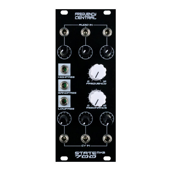
State 700 MK2
Based on the Roland System 700 state variable voltage controlled filter
Main PCB
Pots 'n' sockets PCB
Key to PCB screen print:
n: This signifies NPN BC547 transistors. Note the correct pinout as shown by the half circles.
p: This signifies PNP BC557 transistors. Note the correct pinout as shown by the half circles.
The PCB shows the correct orientation for BC547/BC557. Other transistor types can be used (eg
2N3904/2N3906), but please observe the correct pinout.
Please observe the correct polarity of the electrolytic capacitors.
Advertisement
Table of Contents

Related Manuals for Frequency Central State 700 MK2


Summary of Contents for Frequency Central State 700 MK2
- Page 1 Frequency central Build documentation for: State 700 MK2 Based on the Roland System 700 state variable voltage controlled filter Main PCB Pots ‘n’ sockets PCB Key to PCB screen print: n: This signifies NPN BC547 transistors. Note the correct pinout as shown by the half circles.
- Page 2 Bill of Materials 47R x 1 470pF x 2 TL071 x 1 A100K x 3 100R x 3 1uF x 3 (non polarised) TL072 x 2 these)* 1K x 3 10uF x 1 LM13700 x 1 1K5 x 2 22uF electrolytic x 2 BC547 x 1 B100K x 3 4K7 x 1...
- Page 3 Main PCB assembly Solder all resistors. 2. Solder all IC sockets 3. Solder both 470pF capacitors 4. Solder both transistors 5. Solder all electrolytic capacitors and 3 x 1uF capacitors 6. Solder the power header – if you’re using box type, observe correct polarity 7.
- Page 4 Note: Not all pots and sockets are equal in height. Providing you use the ones in the links provided, everything will line up perfectly. Make sure that you plug the Main PCB into the Pots ‘n’ sockets PCB the right way around – Frequency Central logo should be the right way up.
- Page 5 Calibration 1. V/Oct trimmer: turn Resonance all the way to self oscillation. Patch a 1V/oct source into CV input 1, with the attenuator fully clockwise. Play octaves and adjust the V/Oct trimmer until they are spot on. 2. Offset trimmer: you want to tweak this so that the filter is fully open when the Cutoff pot is fully clockwise.
Need help?
Do you have a question about the State 700 MK2 and is the answer not in the manual?
Questions and answers