Advertisement
Frequency central
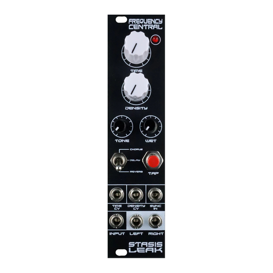
Stasis Leak is a 48kHz DSP effects module, providing a choice of stereo chorus, stereo plate reverb
and tap tempo delay. Stasis Leak is based around a Belton ABE-FX sub board, which in turn is based
around a Coolaudio V1000 chip.
Stasis Leak features 3 PCBs:
•
•
•
Belton ABE-FX, a fully populated SMD PCB which plugs into the Pots 'n' sockets PCB
Build documentation for:
Stasis Leak
Chorus/tap delay/plate reverb
Main PCB
Sockets PCB
Advertisement
Table of Contents

Related Manuals for Frequency Central Stasis Leak


Summary of Contents for Frequency Central Stasis Leak
- Page 1 Stasis Leak is a 48kHz DSP effects module, providing a choice of stereo chorus, stereo plate reverb and tap tempo delay. Stasis Leak is based around a Belton ABE-FX sub board, which in turn is based around a Coolaudio V1000 chip.
- Page 2 Key to PCB screen print: n: This signifies NPN BC547 transistor. Note the correct pinout as shown by the half circles. The PCB shows the correct orientation for BC547. Other transistor types can be used (eg 2N3904), but please observe the correct pinout. Please observe correct polarity of the electrolytic caps, voltage regulators, transistor, ICs etc! Bill of Materials 33R x 1...
- Page 3 Main PCB: Populate the Main PCB front first, as shown on the silkscreen, starting with the lowest profile components, so: • Resistors, diodes • IC sockets • Non-electrolytic capacitors, transistor and voltage regulator • Panel mount components (pots, switches, LED) – it can be useful to use the panel to make sue of nice fit.
- Page 4 Sockets PCB • Place all sockets on the PCB, then place the panel over them. This will assure that the sockets are correctly positioned. Flip the whole lot over and solder the sockets into place. • Cut the male header to size and place the long end into the female header of the Main PCB •...
- Page 5 0V as possible. With Stasis Leak powered up, take a patch lead from the Left output. Using crocodile clips, hook up the tip to the red probe of your DMM, and the sleeve to the black probe of your DMM. Adjust the trimmer until the voltage measurement is 0V or thereabouts.
Need help?
Do you have a question about the Stasis Leak and is the answer not in the manual?
Questions and answers