Advertisement
Table of Contents
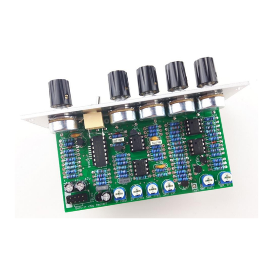
Frequency central
Build documentation for:
xvcO
Based on the Roland System 100M VCO.
XVCO has at it's heart a transistor array chip, usually a CA3046. These are getting a little harder to
source recently, so this PCB has the option to instead use a surface mount LM3046*. Alternatively,
the eastern European UL1111 can be substituted. This PCB incorporates an onboard chip heater for
the transistor array chip.
* If using a surface mount transistor array substitute the 18K resistor for 2 x 33K resistors in parallel.
Key to PCB screen print:
n: This signifies NPN BC547 transistors. Note the correct pinout as shown by the half circles.
p: This signifies PNP BC557 transistors. Note the correct pinout as shown by the half circles.
f: This signifies 2N5485 FETs. Note the correct pinout as shown by the half circles.
The PCB shows the correct orientation for BC547/BC557. Other transistor types can be used
(eg 2N3904/2N3906), but please observe the correct pinout. Please observe the correct
polarity of the electrolytic capacitors.
Advertisement
Table of Contents

Related Manuals for Frequency Central XVCO


Summary of Contents for Frequency Central XVCO
- Page 1 Based on the Roland System 100M VCO. XVCO has at it’s heart a transistor array chip, usually a CA3046. These are getting a little harder to source recently, so this PCB has the option to instead use a surface mount LM3046*. Alternatively, the eastern European UL1111 can be substituted.
- Page 2 Bill of Materials 33R x 1 22pF x 1 CA3046, LM3046 or 16mm B100K x 5 (remove plastic shroud) 100R x 2 100pF x 1 UL1111 820R x 1 470pF x 1 1K trimmer x 1 1K x 3 2.2nF x 2 TL072 x 4 2K trimmer x 2* 1.2K x 1...
- Page 3 Assembly 1. Solder all resistors 2. Solder all IC sockets 3. Solder all non electrolytic capacitors 4. Solder all transistors – watch the polarity! 5. Solder the power header. 6. Solder all electrolytic capacitors 7. Solder all trimmers 8. Solder all potentiometers 9.
- Page 4 • 2K2 Lin: High end trim. There is a set-up procedure for this in the Roland service manual (pages 5 and 6 of this PDF). It requires the use of a ‘scope and a precision reference oscillator. I’ve built a fair few of these by now, and I’ve found it tracks very well over 6-7 octaves even before using Roland’s set-up procedure for high end trim –...
Need help?
Do you have a question about the XVCO and is the answer not in the manual?
Questions and answers