Advertisement
Frequency central
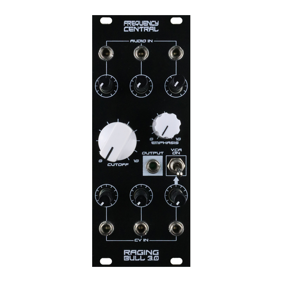
Raging bull 3.0
A big part of the sound of the Taurus was the way in which the VCF interfaced with the VCA, so on
Raging Bull the VCA is always in the audio path. A toggle switch allows you to select 'always open' or
CV control of the VCA from CV input 3. This is a very flexible arrangement, for example:
1. By sending an ADSR into CV3, the signal will go to the VCA CV input unattenuated and the
VCF CV input via the attenuator
2. By sending a gate into CV3, and setting the attenuator to zero, the VCA can be gated while
the gate has no affect on the VCF
Key to PCB screen print:
n: This signifies NPN BC547 transistors. Note the correct pinout as shown by the half circles.
p: This signifies PNP BC557 transistors. Note the correct pinout as shown by the half circles.
The PCB shows the correct orientation for BC547/BC557. Other transistor types can be used (eg
2N3904/2N3906), but please observe the correct pinout.
Please observe the correct polarity of the electrolytic capacitors.
Build documentation for:
Based on the legendary Moog Taurus Mk I VCF and VCA.
Advertisement
Table of Contents

Related Manuals for Frequency Central Raging Bull 3.0


Summary of Contents for Frequency Central Raging Bull 3.0
- Page 1 Frequency central Build documentation for: Raging bull 3.0 Based on the legendary Moog Taurus Mk I VCF and VCA. A big part of the sound of the Taurus was the way in which the VCF interfaced with the VCA, so on Raging Bull the VCA is always in the audio path.
- Page 2 Bill of Materials 330R x 1 470pF x 2 CA3046* A100K x 3 470R x 1 10nF x 1 TL072 these)** 1K x 8 100nF x 5 LM13700 2K2 x 2 220nF x 2 BC547 x 8 B100K x 3 2K7 x 2 10uF electrolytic x 2 BC557 x 2...
- Page 3 Main PCB assembly Solder all resistors. Tip #1 - don’t mix up the 2K2 and 2M2 Tip #2 - don’t mix up the 470R and 470K 2. Solder all IC sockets 3. Solder all non-electrolytic capacitors 4. Solder all transistors 5.
- Page 4 Note: Not all pots and sockets are equal in height. Providing you use the ones in the links provided, everything will line up perfectly. Make sure that you plug the Main PCB into the Pots ‘n’ sockets PCB the right way around – Frequency Central logo should be the right way up.
- Page 5 Calibration 1. VCA trimmer: flick the toggle switch down, send a nice snappy ADSR into CV3 input. Adjust Bias trimmer to sweet spot, ie there is no DC thump. The chances are that that the sweet spot is around the mid position. 2.
Need help?
Do you have a question about the Raging Bull 3.0 and is the answer not in the manual?
Questions and answers