Advertisement
Table of Contents
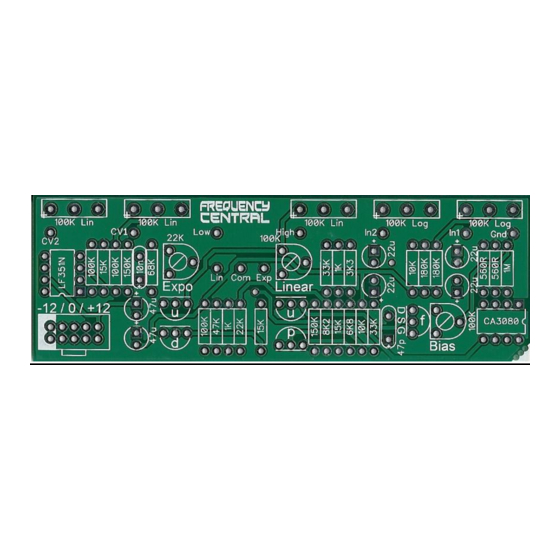
Build documentation for:
System X Amplifier
Based on the Roland System 100M VCA
Frequency central
Version 2 / April 2013
B100K
B100K
B100K
A100K
A100K
CV2
CV1
Initial
Input 1
Input 2
Gain
Key to PCB screen print:
n: This signifies NPN BC547 transistors. Note the correct pinout as shown by the half circles.
p: This signifies PNP BC557 transistors. Note the correct pinout as shown by the half circles.
f: This signifies 2N5485 FETs. Note the correct pinout as shown by the half circles.
Gnd: Ground
Please observe the correct polarity of the 6 electrolytic capacitors. The 4 x 22uF are
configured in sets of 2 back to back (negative to negative).
The PCB shows the correct orientation for BC547/BC557/2N5485. Other transistor types can
be used (eg 2N3904/2N3906/BF245), but please observe the correct pinout.
Advertisement
Table of Contents

Related Manuals for Frequency Central System X Amplifier


Summary of Contents for Frequency Central System X Amplifier
- Page 1 Build documentation for: System X Amplifier Based on the Roland System 100M VCA Frequency central Version 2 / April 2013 B100K B100K B100K A100K A100K Initial Input 1 Input 2 Gain Key to PCB screen print: n: This signifies NPN BC547 transistors. Note the correct pinout as shown by the half circles.
- Page 2 Trimmers Bias: Adjust Bias trimmer to sweet spot, ie a nice clean undistorted VCA output with no thunk when a snappy ADSR is applied to a CV input. I do this without any audio at the inputs. The chances are that that the sweet spot is around the mid position. Linear: I tend to turn this to around fully anticlockwise.
Need help?
Do you have a question about the System X Amplifier and is the answer not in the manual?
Questions and answers