Table of Contents
Advertisement
Quick Links
Smart encoders & actuators
IFS-10-PM
programming
& display
unit
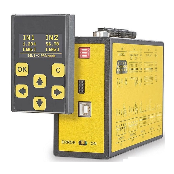
• Programming and display unit for IFS-10 safety monitor
• Touchscreen with intuitive navigation
• 1.54" OLED display (128 x 64 pixel)
• Simple parametrization of IFS-10 monitors
• Allows to edit, save, and load the parameters
Suitable for the following models:
IFS-10-PM
•
Lika Electronic
User's guide
•
Tel. +39 0445 806600
General Contents
Preliminary information
1 - Safety summary
2 - Identification
3 – Technical features
4 - Electrical connections
5 - Parametrization of the safety unit
6 - IFS-10-PM parameters list
7 - Example of an individual scalable display 35
8 - Error Messages
•
info@lika.biz
10
11
14
15
27
37
•
www.lika.biz
7
8
Advertisement
Table of Contents

Related Manuals for Lika IFS-10-PM


Summary of Contents for Lika IFS-10-PM
- Page 1 • 2 - Identification 3 – Technical features 4 - Electrical connections 5 - Parametrization of the safety unit 6 - IFS-10-PM parameters list 7 - Example of an individual scalable display 35 8 - Error Messages Lika Electronic •...
- Page 2 Tous droits réservés. This document and information contained herein are the property of Lika Electronic s.r.l. and shall not be reproduced in whole or in part without prior written approval of Lika Electronic s.r.l. Translation, reproduction and total or partial modification (photostat copies, film and microfilm included and any other means) are forbidden without written authorisation of Lika Electronic s.r.l.
-
Page 3: Table Of Contents
Load Data From Safety Unit..........................21 Load Data From Display Memory........................21 5.6.2 Messages when loading the parameters......................22 ATTENTION! No Data In Flash........................22 5.6.3 Loading the parameters of IFS-10-PM......................22 5.7 Edit parameters.................................23 Edit Data..................................23 5.8 Save parameters................................24 Save Data To................................24 5.8.1 Saving the parameters to the Safety Unit....................24 Save Data To Safety Unit.............................24... - Page 4 5.8.3 Messages when saving the parameters......................25 Please Confirm!..............................25 To Exit Without Save Press OK........................25 5.9 Entering the pin value..............................25 6 - IFS-10-PM parameters list........................27 Input Scaling for display 3 and 4..........................29 X Factor 1..................................29 / Divisor 1..................................29 +/- Value 1...................................29...
- Page 5 Subject Index ATTENTION! No Data In Flash........22 Safety unit...............19 Save Data To Display Memory........24 Save Data To Display Unit..........24 Communication Offline..........38 Save Data To Safety Unit..........24 CRC Error................38 Screen Light..............31 Screen Saver..............31 Decimal Point 1..............29 Serial Baud Rate............33 Decimal Point 2..............30 Serial Error...............38 Display 1: Frequencies (Hz)........16 Serial Format..............33...
-
Page 6: Typographic And Iconographic Conventions
Typographic and iconographic conventions In this guide, to make it easier to understand and read the text the following typographic and iconographic conventions are used: parameters and objects both of the device and the interface are coloured in GREEN; • alarms are coloured in RED;... -
Page 7: Preliminary Information
Thanks to its intuitive operation, the IFS-10-PM display is quick, easy, and flexible to handle. The unit can be used via PC or connected directly to the safety unit. The IFS-10-PM offers a wide range of functions and features (depending on the type of safety device and the DIL switch settings). -
Page 8: Safety Summary
failure to comply with these precautions or with specific warnings elsewhere in this manual violates safety standards of design, manufacture, and intended use of the equipment; Lika Electronic assumes no liability for the customer's failure to comply with these requirements. Electrical safety ... -
Page 9: Mechanical Safety
IFS-10-PM programming & display unit Mechanical safety Install the device following strictly the information in the “3 – Technical features” section on page 11; mechanical installation has to be carried out with power supply disconnected and stationary mechanical parts;... -
Page 10: Identification
Information is listed in the delivery document too. Please always quote the order code and the serial number when reaching Lika Electronic for purchasing spare parts or needing assistance. For any information on the technical characteristics of the product refer to the technical catalogue. -
Page 11: Technical Features
IFS-10-PM programming & display unit 3 – Technical features WARNING Installation and maintenance operations have to be carried out by qualified personnel only, with power supply disconnected and mechanical parts compulsorily in stop. 3.1 Overall dimensions Frontal view Lateral view Figure 1 3.2 Installation... -
Page 12: Mounting The Display Unit On The Ifs-10 Safety Unit
3.3 Mounting the display unit on the IFS-10 safety unit The mounting of the IFS-10-PM programming and display unit is performed by simply plugging it into the IFS-10 safety device. Via the 8-pin connector 3 both units are electrically connected. -
Page 13: Cleaning, Maintenance, And Service Notes
IFS-10-PM programming & display unit 3.4 Cleaning, maintenance, and service notes WARNING Switch the power off before cleaning the front screen. To clean the front side and the display of the unit please always use a soft, clean, slightly damp (not wet!) cloth such as a microfibre or cotton cloth to remove the dust from the display. -
Page 14: Electrical Connections
IFS-10-PM rear view 8-pin male connector The 8-pin male connector electrically connects the IFS-10-PM to the safety unit. For information on the mechanical installation refer also to the “3.3 Mounting the display unit on the IFS-10 safety unit” section on page 12. -
Page 15: Parametrization Of The Safety Unit
IFS-10-PM programming & display unit 5 - Parametrization of the safety unit 5.1 Using the keypad The IFS-10-PM is operated by using the six buttons available in the touchscreen key panel. The OK button is used to confirm the entries. -
Page 16: Normal Operation" Mode
In this mode, the input frequency of the sensor 1 is converted according to the parameters set in the OPU menu of the safety unit and then shown on the display. Refer also to the “6 - IFS-10-PM parameters list” section on page 27 *. Display 4: Scaled Input 2... -
Page 17: Factory Settings" Mode
In order to preserve the current parameter settings of the safety unit for future needs, they can be stored in the flash memory of the IFS-10-PM unit. The parameters must be transmitted from the safety unit to the IFS-10-PM first (see the “5.6 Load parameters”... -
Page 18: Programming" Mode
5.5 “PROGRAMMING“ mode The DIL switch positions of the safety unit are: In this mode the parameters of the IFS-10-PM unit or the parameters of the IFS-10 safety unit can be edited via the touch panel. 5.5.1 IFS-10-PM menu structure NOTE Please find the IFS-10-PM parameters list in the “6 - IFS-10-PM parameters list”... -
Page 19: Menu Structure Of The Safety Unit
See the “5.6 Load parameters” section on page 21. Load Data From Display Memory To load the parameters for the safety unit from the flash memory of the IFS-10-PM Load Data From display unit, please select Display Memory and then press the OK button to confirm. - Page 20 IFS-10-PM programming & display unit Edit Data edit the IFS-10 safety unit Edit Data parameters please select then press the OK button to confirm. See the “5.7 Edit parameters” section on page 23. Save Data To Safety Unit To save the parameters in the IFS-10...
-
Page 21: Load Parameters
Use Loaded Data This menu option can be selected only when data has already been loaded from either the IFS-10 safety unit or the flash memory of the IFS-10-PM display unit. To edit the already loaded parameters, please select Use Loaded Data and then press the OK button to confirm. -
Page 22: Messages When Loading The Parameters
5.6.3 Loading the parameters of IFS-10-PM The Load Data From... menu is only available for the parameters of the IFS-10 safety unit. The parameters for the IFS-10-PM unit are loaded directly after Display Unit is selected in the first menu level. -
Page 23: Edit Parameters
After choosing the device to be edited in the first menu level press the selectable parameters are shown. All the available parameters are listed in the menu. For the IFS-10-PM display unit parameters see the “6 - IFS-10-PM parameters list” section on page 27. For the IFS-10 safety unit parameters refer to the “User's manual”... -
Page 24: Save Parameters
OK button to confirm. Save Data To Display Memory To save the parameters of the IFS-10 safety unit on the flash memory of the IFS-10-PM display unit, Save Data To Display Memory please select then press the OK button to confirm. -
Page 25: Messages When Saving The Parameters
After pressing the OK button, the changed PIN must be saved in order that the IFS-10-PM display unit is protected with the new PIN value starting from the next power-on (see the “5.8 Save parameters“ section on page 24). - Page 26 IFS-10-PM programming & display unit To enable the operation of the IFS-10-PM display unit keypad, the PIN must be entered and confirmed by pressing the OK button. WARNING Should the individual PIN be forgotten or lost, you can enter the emergency pin 6079.
-
Page 27: Ifs-10-Pm Parameters List
* If the version of the safety device is lower than 04A, the scaling parameters are in the IFS-10-PM unit. If the version of the safety device is higher than 04A, the scaling parameters are available in the “OPU menu” of the safety device. -
Page 28: Unit Settings
IFS-10-PM programming & display unit The parameters for “Unit Settings” and “Serial Settings” are listed in the following menu: Display Unit Edit Data … Settings Parameter Group Parameter Default Unit Settings Display Mode Screen Light Screen Saver... - Page 29 IFS-10-PM programming & display unit Input Scaling for display 3 and 4 For Display 3: Scaled Input 1 and Display 4: Scaled Input 2, refer to the “5.3 “NORMAL OPERATION“ mode” section on page 16. NOTE If the version of the safety device is higher than 04A, this menu is available in the safety device as “OPU menu”.
- Page 30 IFS-10-PM programming & display unit +/- Value 2 +/- Value 1 -999999 999999 Units 2 Units 1 Decimal Point 2 Decimal Point 1 NOTE Parameters marked with “2” in the name are applied to the input frequency 2 and used to show the value in the display mode 4.
- Page 31 IFS-10-PM programming & display unit Unit Settings Parameter Max Default Display Mode It sets which of the four display modes has to be used as start display (see the “5 - Parametrization of the safety unit” section on page 15).
- Page 32 IFS-10-PM programming & display unit Screen Light Screen Saver * Changes in the parameter values are effective immediately, but they are lost if not saved (see the “5.8 Save parameters” section on page 24)! MAN IFS-10-PM EN 1.1.odt 6 - IFS-10-PM parameters list...
- Page 33 Serial Init This parameter allows to set the baud rate for the transmission of the initialization values to the OS software tool or to the IFS-10-PM programming and display unit. 0: The initialization values will be transmitted at 9600 baud. After initialization the unit operates again according to the user's settings.
- Page 34 IFS-10-PM programming & display unit to the user's settings. Using a baud rate higher than 9600 baud, the duration of the initialization procedure will be shortened. MAN IFS-10-PM EN 1.1.odt 6 - IFS-10-PM parameters list 34/44...
-
Page 35: Example Of An Individual Scalable Display
If the version of the safety device is lower than 04A, the scaling parameters are in the IFS-10-PM unit. If the version of the safety device is higher than 04A, the scaling parameters are available in the “OPU menu” of the safety device. - Page 36 For any information on the Display 1: Frequencies (Hz) and the Display 3: Scaled Input 1 / Display 4: Scaled Input 2 please refer to the “5.3 “NORMAL OPERATION“ mode” section on page 16. MAN IFS-10-PM EN 1.1.odt 7 - Example of an individual scalable display 36/44...
-
Page 37: Error Messages
IFS-10-PM programming & display unit 8 - Error Messages Error and status messages will be shown in the info line of the IFS-10-PM display unit. 8.1 Error messages from the Safety Unit Runtime Error Initial Error (Runtime Error Initial Error) is invoked from the... -
Page 38: Status Messages From Ifs-10-Pm
IFS-10-PM programming & display unit 8.2 Status messages from IFS-10-PM Error and status messages will be shown in the info line of the IFS-10-PM display unit. Communication Offline Communication Offline If the status message appears on the display: • the safety unit must be switched off and then on again in order to re-initialize the safety and display unit;... -
Page 39: Technical Specifications
IFS-10-PM programming & display unit 9 - Technical Specifications Power supply Input voltage: directly via a safety unit Protection: mechanical polarity protection Power consumption: approx. 100 mA Connection: 8 position pin strip Display elements Display: 1.54“ OLED display Resolution: 128 x 64 pixels... -
Page 40: Default Parameters List
IFS-10-PM programming & display unit 10 – Default parameters list Parameters list Default value Input Scaling for display 3 and 4 X Factor 1 / Divisor 1 +/- Value 1 Units 1 Decimal Point 1 X Factor 2 / Divisor 2... - Page 41 This page intentionally left blank...
- Page 42 This page intentionally left blank...
- Page 43 This page intentionally left blank...
- Page 44 01a, 02a information removed, address setting, 02b, 02c, 05.05.2022 changing the scaled input, new parameters added 03a, 03b, 04a Lika Electronic Via S. Lorenzo, 25 • 36010 Carrè (VI) • Italy Tel. +39 0445 806600 Fax +39 0445 806699 info@lika.biz •...
Need help?
Do you have a question about the IFS-10-PM and is the answer not in the manual?
Questions and answers