Table of Contents
Advertisement
Quick Links
Smart encoders & actuators
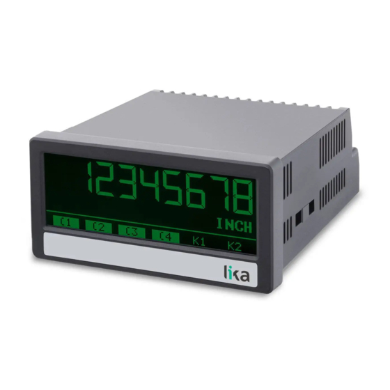
LD210
• Touch-screen process indicator for analogue encoders
• Two 16 bit analogue inputs -10/0 ... +10V, 0/4 ... 20mA
• Displays input 1, input 2 or a combination of the inputs (IN1+IN2,
IN1-IN2, IN1xIN2, IN1/IN2)
• Digital, analogue, serial and relay outputs
• DC / AC power supply: 18÷30Vdc or 115÷230Vac
Suitable for the following models:
LD210 touch-screen display
•
LD210-PM
•
115/230Vac power supply
LD210-DO touch-screen display with four
•
control outputs + RS-232 serial interface
LD210-AVI
•
analogue output + four control outputs +
RS-232 serial interface
LD210-RO touch-screen display with two
•
relay outputs
Lika Electronic
User's guide
touch-screen
display
touch-screen
display
•
Tel. +39 0445 806600
General Contents
Preliminary information
with
1 - Safety summary
2 - Identification
3 - Mounting instructions
4 - Electrical connections
with
5 - Display and touch screen
6 – Menus and parameters
7 - Appendix
8 - Parameters / serial codes
•
info@lika.biz
10
12
14
15
17
26
28
84
85
•
www.lika.biz
Advertisement
Table of Contents

Subscribe to Our Youtube Channel
Related Manuals for Lika LD210


Summary of Contents for Lika LD210
- Page 1 Preliminary information LD210-PM touch-screen display with • 1 - Safety summary 115/230Vac power supply 2 - Identification LD210-DO touch-screen display with four • 3 - Mounting instructions control outputs + RS-232 serial interface 4 - Electrical connections LD210-AVI touch-screen display with •...
- Page 2 Tous droits réservés. This document and information contained herein are the property of Lika Electronic s.r.l. and shall not be reproduced in whole or in part without prior written approval of Lika Electronic s.r.l. Translation, reproduction and total or partial modification (photostat copies, film and microfilm included and any other means) are forbidden without written authorisation of Lika Electronic s.r.l.
-
Page 3: Table Of Contents
General contents General contents..............................3 Subject index............................... 7 Typographic and iconographic conventions....................9 Preliminary information..........................10 Operational modes..................................10 Functional diagram..................................11 1 - Safety summary............................12 1.1 Safety......................................12 1.2 Electrical safety..................................12 1.3 Mechanical safety................................12 2 - Identification.............................. 14 3 - Mounting instructions..........................15 3.1 Overall dimensions................................15 3.2 Installation.....................................16 3.3 Cleaning, maintenance and service notes........................16... - Page 4 value.....................................36 Decimal point..................................36 Scale units...................................37 Sampling time (s)................................38 Average filter..................................38 Offset.....................................39 Linearization..................................39 Totalization..................................39 6.4 IN 1 linearization menu..............................40 P1(X).......................................40 P24(X)....................................40 P1(Y).......................................40 P24(Y)....................................40 6.4.1 Description of the linearisation function......................40 6.5 IN 1 totalization menu..............................43 Time base.....................................43 Divider....................................43 Decimal point..................................44 Scale units...................................44 6.6 IN 2 properties menu.................................46 Configuration..................................46 Start...
- Page 5 Preselection 2..................................59 Preselection 3..................................59 Preselection 4..................................60 6.11 Preselection 1 menu................................61 Source 1....................................61 Mode 1....................................61 Hysteresis 1..................................63 Pulse time 1 (s)................................63 Output target 1................................63 Output polarity 1................................63 Output lock 1..................................64 Start up delay 1 (s)................................64 Event color 1..................................64 6.12 Preselection 2 menu................................65 Source 2....................................65 Mode...
- Page 6 Serial timer (s)..................................73 Serial value..................................73 6.16 Analog OUT menu................................74 Analog source...................................74 Analog format..................................75 Analog start..................................75 Analog end..................................75 Analog gain (%)................................75 Analog offset %................................76 6.17 Command menu................................77 Input 1 action...................................77 Input 1 config...................................79 Input 2 action...................................79 Input 2 config...................................79 Input 3 action...................................79 Input 3 config...................................79...
- Page 7 Subject index Mode 3..................67 Mode 4..................69 Additive value..............56 Analog end................75 Analog format..............75 Offset................39, 49 Analog gain (%)..............75 Operational mode............34 Analog offset %..............76 Output lock 1..............64 Analog source..............74 Output lock 2..............66 Analog start................75 Output lock 3..............68 Average filter..............38, 48 Output lock 4..............70 Output polarity 1.............63 Output polarity 2.............65 Back up memory...............35...
- Page 8 Source dual down............81 Start value..............36, 46 Source dual top..............81 Source single..............80 Time base..............43, 53 Start display................80 Totalization..............39, 49 Start up delay 1 (s)............64 Start up delay 2 (s)............66 Unit number...............71 Start up delay 3 (s)............68 Up-date-time..............83 Start up delay 4 (s)............70...
-
Page 9: Typographic And Iconographic Conventions
Typographic and iconographic conventions In this guide, to make it easier to understand and read the text the following typographic and iconographic conventions are used: parameters and objects both of the device and the interface are coloured in GREEN; • alarms are coloured in RED;... -
Page 10: Preliminary Information
In the series the following models are available: LD210 touch-screen indicator standard version; • LD210-PM provides additional 115-230Vac power supply; • LD210-AVI provides additional 16-bit analogue output, four control outputs and RS-232 serial • interface; LD210-DO further offers four control outputs and RS-232 serial interface; •... -
Page 11: Functional Diagram
Operational mode DUAL (input A and input B are both used), see the parameter in the “6.2 • General menu” section on page 34. ◦ Two channel operation of input 1 and input 2 Operational mode IN 1 + IN 2 (input A and input B are both used), see the parameter in the “6.2 •... -
Page 12: Safety Summary
• failure to comply with these precautions or with specific warnings elsewhere in this manual violates safety standards of design, manufacture, and intended use of the equipment; • Lika Electronic assumes no liability for the customer's failure to comply with these requirements. 1.2 Electrical safety •... - Page 13 LD210 • delicate electronic equipment: handle with care; • do not subject the device to knocks or shocks; • respect the environmental characteristics of the device. MAN LD210 E 1.0.odt 1 - Safety summary 13 of 96...
-
Page 14: Identification
Information is listed in the delivery document too. Please always quote the order code and the serial number when reaching Lika Electronic for purchasing spare parts or needing assistance. For any information on the technical characteristics of the product, refer to the technical catalogue. -
Page 15: Mounting Instructions
Mount the display into the provided cut-out (w x h approx. 91 x 43 mm, 3.58” x 1.69’’) without panel clips. Install panel clips on the display housing and screw until the unit is fixed. Panel cut out: 91 x 43 mm (3.58” x 1.69’’) MAN LD210 E 1.0.odt 3 - Mounting instructions 15 of 96... -
Page 16: Installation
(if necessary). Unauthorized opening and repair operations can have negative effects or cause failures to the protection measures of the unit. MAN LD210 E 1.0.odt 3 - Mounting instructions 16 of 96... -
Page 17: Electrical Connections
GND + 4 – Aux. Out, see the “4.3 Auxiliary voltage output” section on page 18). All GND terminal blocks are internally connected. NOTE For AC power supply (PM order code) see the following section. MAN LD210 E 1.0.odt 4 - Electrical connections 17 of 96... -
Page 18: Ac Power Supply (Pm Order Code)
150 mA up to 45° Celsius. At power supply voltage at terminal blocks 1 and 2 higher temperature the maximum output current is and should be loaded with max. 250 mA. reduced to 80 mA. MAN LD210 E 1.0.odt 4 - Electrical connections 18 of 96... -
Page 19: Analogue Inputs
36 and the “6.6 IN 2 properties menu” section on page 46 respectively. WARNING The characteristics of the inputs (voltage level or current level) must be set before connecting the encoder! 4.4.1 Wiring of the analogue inputs MAN LD210 E 1.0.odt 4 - Electrical connections 19 of 96... -
Page 20: Reference Output
The unit provides a 10 V reference output through terminal block 8. The output should be loaded with max. 10 mA. This reference output can be used to connect a potentiometer. 4.5.1 Wiring of the reference output with potentiometer MAN LD210 E 1.0.odt 4 - Electrical connections 20 of 96... -
Page 21: Control Inputs
GND (-) and the corresponding input (+). A capacity of 10 µF will reduce the input frequency to 20 Hz and miscounting due to contact bouncing will be eliminated. MAN LD210 E 1.0.odt 4 - Electrical connections 21 of 96... -
Page 22: Analogue Output (Avi Order Code)
The analogue output is proportional to the reference source and is referenced to potential AGND. AGND and GND are internally connected. WARNING Voltage and current outputs of the analogue output cannot be operated simultaneously. MAN LD210 E 1.0.odt 4 - Electrical connections 22 of 96... -
Page 23: Serial Interface (Avi And Do Order Codes)
• to read out internal states and current measuring values via PC or PLC The following drawing shows the connection to a PC by using a standard D-Sub 9-pin connector: MAN LD210 E 1.0.odt 4 - Electrical connections 23 of 96... -
Page 24: Control Outputs (Avi And Do Order Codes)
The switching voltage of the outputs must be applied to input terminal block 19 (COM+). In case of switching inductive loads it is advisable to use an external filtering of the coils. 4.9.1 Wiring of the control outputs MAN LD210 E 1.0.odt 4 - Electrical connections 24 of 96... -
Page 25: Relay Outputs (Ro Order Code)
AC switching capacity max. 250 Vac / max. 3 A / 750 VA DC switching capacity max. 150 Vdc / max. 2 A / 50 W 4.10.1 Wiring of the relay outputs MAN LD210 E 1.0.odt 4 - Electrical connections 25 of 96... -
Page 26: Display And Touch Screen
You can exit the editing of the parameter by pressing the key. Parameter changes become active only after closing the selection of the menu. MAN LD210 E 1.0.odt 5 - Display and touch screen 26 of 96... -
Page 27: Screen Structure During Operation
It is available only with AVI, DO and RO order codes. Display with current, minimum and maximum values of input 1 and input 2. To switch to the next display, press the touch screen. MAN LD210 E 1.0.odt 5 - Display and touch screen 27 of 96... -
Page 28: Menus And Parameters
(see on page 39) is set to either “1 – 1 QUADRANT” or “2 – 4 QUADRANT”. IN 1 Linearization menu, see the “6.4 IN 1 linearization menu” section on page 40 P1(X), see on page 40 MAN LD210 E 1.0.odt 6 – Menus and parameters 28 of 96... - Page 29 49) is set to either “1 – 1 QUADRANT” or “2 – 4 QUADRANT”. IN 2 Linearization menu, see the “6.7 IN 2 linearization menu” section on page 50 P1(X), see on page 50 MAN LD210 E 1.0.odt 6 – Menus and parameters 29 of 96...
- Page 30 Preselection values menu, see the “6.10 Preselection values menu” section on page 59 Preselection 1, see on page 59 Preselection 2, see on page 59 Preselection 3, see on page 59 Preselection 4, see on page 60 MAN LD210 E 1.0.odt 6 – Menus and parameters 30 of 96...
- Page 31 3, see on page 67 Output lock 3, see on page 68 Start up delay 3 (s), see on page 68 Event color 3, see on page 68 MAN LD210 E 1.0.odt 6 – Menus and parameters 31 of 96...
- Page 32 75 Analog start, see on page 75 Analog end, see on page 75 Analog gain (%), see on page 75 Analog offset %, see on page 76 MAN LD210 E 1.0.odt 6 – Menus and parameters 32 of 96...
- Page 33 Color, see on page 82 Brightness, see on page 82 Contrast, see on page 82 Screen saver, see on page 83 Up-date-time, see on page 83 Font, see on page 83 MAN LD210 E 1.0.odt 6 – Menus and parameters 33 of 96...
-
Page 34: General Menu
This parameter sets the PIN code for the lock function of all parameters. The Master PIN is 6079. 0000 No lock Parametrization of the unit after entering PIN code 9999 9999 MAN LD210 E 1.0.odt 6 – Menus and parameters 34 of 96... -
Page 35: Back Up Memory
After reset you will have to repeat your individual set-up procedure. 0 NO No default values are loaded 1 YES Load default values of all parameters MAN LD210 E 1.0.odt 6 – Menus and parameters 35 of 96... -
Page 36: In 1 Properties Menu
Decimal point placed in the specified position 4 0000.0000 Decimal point placed in the specified position 5 000.00000 Decimal point placed in the specified position 6 00.000000 Decimal point placed in the specified position MAN LD210 E 1.0.odt 6 – Menus and parameters 36 of 96... -
Page 37: Scale Units
15 cm 16 m 17 inch 18 feet 19 C 20 F 21 K 22 1/sec 23 1/min 24 1/h 25 gal/min 26 Pa 27 kPa 28 % MAN LD210 E 1.0.odt 6 – Menus and parameters 37 of 96... -
Page 38: Sampling Time (S)
2 cycle average Floating average within 2 cycles 4 cycle average Floating average within 4 cycles 8 cycle average Floating average within 8 cycles 16 cycle average Floating average within 16 cycles MAN LD210 E 1.0.odt 6 – Menus and parameters 38 of 96... -
Page 39: Offset
34). For complete information please refer to the “6.5 IN 1 totalization menu” section on page 43. 0 NO No totalization 1 YES Totalization is active (see on page 43). MAN LD210 E 1.0.odt 6 – Menus and parameters 39 of 96... -
Page 40: In 1 Linearization Menu
(interpolation points) are available, they can be freely arranged over the whole conversion range at any desired distance. The unit uses linear interpolation between two coordinates. Therefore it is advisable to set several coordinates MAN LD210 E 1.0.odt 6 – Menus and parameters 40 of 96... - Page 41 In this application, the analogue signal information about pressure is proportional to the filling level, but not to the filling quantity. MAN LD210 E 1.0.odt 6 – Menus and parameters 41 of 96...
- Page 42 For the linear part of the tank it is sufficient to set the final pressure value in P16(X) parameter. It is now possible to easily calculate the appropriate filling quantities ad enter P1(Y) P16(Y) the relevant values in the parameters. MAN LD210 E 1.0.odt 6 – Menus and parameters 42 of 96...
-
Page 43: In 1 Totalization Menu
77. Divider This parameter allows to set the divisional factor of the totalization value. No division 1 10 The result of the totalization is divided by 10 MAN LD210 E 1.0.odt 6 – Menus and parameters 43 of 96... -
Page 44: Decimal Point
Decimal point parameter. 1 mV 3 mA 4 km/h 5 mph 6 feet/min 7 inch/min 9 kg 10 oz 11 W 12 kW 13 VA 14 mm 15 cm MAN LD210 E 1.0.odt 6 – Menus and parameters 44 of 96... - Page 45 (by pressing and holding the arrow key down the characters scroll fast). key to save the Edit Unit menu. Press the 29 Edit unit Press the key to close the Edit Unit menu. MAN LD210 E 1.0.odt 6 – Menus and parameters 45 of 96...
-
Page 46: In 2 Properties Menu
No decimal point 1 0000000.0 Decimal point placed in the specified position 2 000000.00 Decimal point placed in the specified position 3 00000.000 Decimal point placed in the specified position MAN LD210 E 1.0.odt 6 – Menus and parameters 46 of 96... -
Page 47: Scale Units
12 kW 13 VA 14 mm 15 cm 16 m 17 inch 18 feet 19 C 20 F 21 K 22 1/sec 23 1/min 24 1/h 25 gal/min MAN LD210 E 1.0.odt 6 – Menus and parameters 47 of 96... -
Page 48: Sampling Time (S)
2 cycle average Floating average within 2 cycles 4 cycle average Floating average within 4 cycles 8 cycle average Floating average within 8 cycles 16 cycle average Floating average within 16 cycles MAN LD210 E 1.0.odt 6 – Menus and parameters 48 of 96... -
Page 49: Offset
34). For complete information please refer to the “6.8 IN 2 totalization menu” section on page 53. 0 NO No totalization 1 YES Totalization is active (see on page 53). MAN LD210 E 1.0.odt 6 – Menus and parameters 49 of 96... -
Page 50: In 2 Linearization Menu
6.7.1 Description of the linearisation function The linearisation function allows to convert a linear input signal into a non- linear representation (or vice versa). 24 programmable X / Y coordinates MAN LD210 E 1.0.odt 6 – Menus and parameters 50 of 96... - Page 51 In this application, the analogue signal information about pressure is proportional to the filling level, but not to the filling quantity. MAN LD210 E 1.0.odt 6 – Menus and parameters 51 of 96...
- Page 52 For the linear part of the tank it is sufficient to set the final pressure value in P16(X) parameter. It is now possible to easily calculate the appropriate filling quantities ad enter P1(Y) P16(Y) the relevant values in the parameters. MAN LD210 E 1.0.odt 6 – Menus and parameters 52 of 96...
-
Page 53: In 2 Totalization Menu
For further 3 COMMAND Input 2 action information please refer to the parameter in the “6.17 Command menu” section on page 77. MAN LD210 E 1.0.odt 6 – Menus and parameters 53 of 96... -
Page 54: Divider
The number of decimal places must be set in the Decimal point parameter. 1 mV 3 mA 4 km/h 5 mph 6 feet/min 7 inch/min 9 kg 10 oz 11 W MAN LD210 E 1.0.odt 6 – Menus and parameters 54 of 96... - Page 55 (by pressing and holding the arrow key down the characters scroll fast). Press the key to save the Edit Unit menu. 29 Edit unit key to close the Edit Unit menu. Press the MAN LD210 E 1.0.odt 6 – Menus and parameters 55 of 96...
-
Page 56: Linkage Properties Menu
Additive value This parameter sets the additive constant that will be added to the result of the combined operation. -99999999 Smallest value +00000000 Default value +99999999 Highest value MAN LD210 E 1.0.odt 6 – Menus and parameters 56 of 96... -
Page 57: Decimal Point
5 mph 6 feet/min 7 inch/min 9 kg 10 oz 11 W 12 kW 13 VA 14 mm 15 cm 16 m 17 inch 18 feet 19 C MAN LD210 E 1.0.odt 6 – Menus and parameters 57 of 96... - Page 58 (by pressing and holding the arrow key down the characters scroll fast). key to save the Edit Unit menu. Press the 29 Edit unit key to close the Edit Unit menu. Press the MAN LD210 E 1.0.odt 6 – Menus and parameters 58 of 96...
-
Page 59: Preselection Values Menu
Preselection / switching point 3. The features of must be set in the Preselection 3 menu, see the “6.13 Preselection 3 menu” section on page -99999999 Smallest value +00003000 Default value +99999999 Highest value MAN LD210 E 1.0.odt 6 – Menus and parameters 59 of 96... -
Page 60: Preselection 4
Preselection / switching point 4. The features of must be set in the Preselection 4 menu, see the “6.14 Preselection 4 menu” section on page -99999999 Smallest value +00004000 Default value +99999999 Highest value MAN LD210 E 1.0.odt 6 – Menus and parameters 60 of 96... -
Page 61: Preselection 1 Menu
Display value Preselection 1 ON Preselection 1 Hysteresis 1 Display value < – 1 |RESULT|<=|PRES| The absolute display value is less than or equal to MAN LD210 E 1.0.odt 6 – Menus and parameters 61 of 96... - Page 62 Display value > + ½ OFF Preselection 1 Hysteresis 1 Display value < - ½ OFF Preselection Trailing 6 RES>=PRES-TRAIL Display value is greater than or equal to MAN LD210 E 1.0.odt 6 – Menus and parameters 62 of 96...
-
Page 63: Hysteresis 1
Output polarity 1 Preselection Polarity for the switching condition of 0 ACTIVE HIGH Switching condition is true Active “HIGH“ 1 ACTIVE LOW Switching condition is true Active “LOW“ MAN LD210 E 1.0.odt 6 – Menus and parameters 63 of 96... -
Page 64: Output Lock 1
1 CHANGE TO RED Colour of display changes to red CHANGE TO Colour of display changes to green GREEN CHANGE TO Colour of display changes to yellow YELLOW MAN LD210 E 1.0.odt 6 – Menus and parameters 64 of 96... -
Page 65: Preselection 2 Menu
2. For complete Polarity for the switching condition of Output polarity 1 information please refer to the parameter in the “6.11 Preselection 1 menu” section on page 61. MAN LD210 E 1.0.odt 6 – Menus and parameters 65 of 96... -
Page 66: Output Lock 2
Event color 1 parameter. For complete information please refer to the Event color 1 parameter in the “6.11 Preselection 1 menu” section on page 61. MAN LD210 E 1.0.odt 6 – Menus and parameters 66 of 96... -
Page 67: Preselection 3 Menu
3. For complete Polarity for the switching condition of Output polarity 1 information please refer to the parameter in the “6.11 Preselection 1 menu” section on page 61. MAN LD210 E 1.0.odt 6 – Menus and parameters 67 of 96... -
Page 68: Output Lock 3
Event color 1 parameter. For complete information please refer to the Event color 1 parameter in the “6.11 Preselection 1 menu” section on page 61. MAN LD210 E 1.0.odt 6 – Menus and parameters 68 of 96... -
Page 69: Preselection 4 Menu
4. For complete Polarity for the switching condition of Output polarity 1 information please refer to the parameter in the “6.11 Preselection 1 menu” section on page 61. MAN LD210 E 1.0.odt 6 – Menus and parameters 69 of 96... -
Page 70: Output Lock 4
Event color 1 parameter. For complete information please refer to the Event color 1 parameter in the “6.11 Preselection 1 menu” section on page 61. MAN LD210 E 1.0.odt 6 – Menus and parameters 70 of 96... -
Page 71: Serial Menu
This parameter allows to set the bit data format. Data Bits Parity Bit Stop Bits 7-EVEN-1 even 7-EVEN-2 even 7-ODD-1 7-ODD-2 7-NONE-1 7-NONE-2 8-EVEN-1 even 8-ODD-1 8-NONE-1 8-NONE-2 MAN LD210 E 1.0.odt 6 – Menus and parameters 71 of 96... -
Page 72: Serial Init
X X X X X X X X = data to be transmitted according to the setting in the value parameter = line feed character = carriage return character Transmission string with serial address Transmission string without serial address MAN LD210 E 1.0.odt 6 – Menus and parameters 72 of 96... -
Page 73: Serial Timer (S)
Result of the combined value of input 1 and input 2 with totalization Minimum value of input 1 Maximum value of input 1 Minimum value of input 2 Maximum value of input 2 MAN LD210 E 1.0.odt 6 – Menus and parameters 73 of 96... -
Page 74: Analog Out Menu
The totalization depends on the selected operational mode, see the table in the Operational mode “6.5 IN 1 totalization menu” section on page 43. See also the parameter on page 34. MAN LD210 E 1.0.odt 6 – Menus and parameters 74 of 96... -
Page 75: Analog Format
If you set “102.00” next to this item the result will be a conversion of 10.2 V or 20.4 mA when the value set next to the Analog end parameter is reached. MAN LD210 E 1.0.odt 6 – Menus and parameters 75 of 96... -
Page 76: Analog Offset
Highest offset EXAMPLE If you set “+00.20” next to this item the result will be an offset of 0.02 V or 0.04 Analog start mA as regards the value. MAN LD210 E 1.0.odt 6 – Menus and parameters 76 of 96... -
Page 77: Command Menu
27). RESET MIN/MAX It resets the min. / max. values. (d) (s) CLEAR LOOP TIME N.A. ACTIVATE N.A. N.A. STORE DATA TESTPROGRAM N.A. MAN LD210 E 1.0.odt 6 – Menus and parameters 77 of 96... - Page 78 LOW / HIGH level (see options 0 – ACTIVE LOW and 1 – ACTIVE HIGH). (d) = dynamic switching (edge evaluation) MAN LD210 E 1.0.odt 6 – Menus and parameters 78 of 96...
-
Page 79: Input 1 Config
This parameter sets the switching characteristics of the input “12 - Ctrl. In 3”. Input 1 config. For complete information please refer to the parameter on page 79. MAN LD210 E 1.0.odt 6 – Menus and parameters 79 of 96... -
Page 80: Display Menu
Maximum value, the reference source is input 1. MINIMUM VALUE Minimum value, the reference source is input 2. MAXIMUM VALUE Maximum value, the reference source is input 2. MAN LD210 E 1.0.odt 6 – Menus and parameters 80 of 96... -
Page 81: Source Dual Top
5 LINKAGE TOTAL operation of input 1 and input 2 with totalization. 6 N.A. Reserved 7 N.A. Reserved 8 MINIMUM VALUE Minimum value, the reference source is input 1. MAN LD210 E 1.0.odt 6 – Menus and parameters 81 of 96... -
Page 82: Color
This parameter sets the brightness of the display expressed in percentage (%). Min. brightness Default value Max. brightness Contrast This parameter sets the viewing angle. Viewing angle from top Viewing angle from centre Viewing angle from bottom MAN LD210 E 1.0.odt 6 – Menus and parameters 82 of 96... -
Page 83: Screen Saver
It does not affect the parameter values. 0.005 Shortest update time 0.100 Default value 9.999 Longest update time Font This parameter sets the font style. Standard Font 1 MAN LD210 E 1.0.odt 6 – Menus and parameters 83 of 96... -
Page 84: Appendix
STX = control character CTRL B (Hex 02) = register code, High Byte = register code, Low Byte xxxxx= readout data ETX = control character CTRL C (Hex 03) BCC = block check character MAN LD210 E 1.0.odt 7 - Appendix 84 of 96... -
Page 85: Parameters / Serial Codes
Start value -99999 +99999 +00000 End value -99999 +99999 +10000 Decimal point Scale units Sampling time (s) 0.0010 60.000 00.010 Average filter Offset -99999 +99999 +00000 Linearization Totalization MAN LD210 E 1.0.odt 8 - Parameters / serial codes 85 of 96... -
Page 86: In 1 Linearization Menu
-99999999 +99999999 +00000000 P16(Y) -99999999 +99999999 +00000000 P17(X) -99999999 +99999999 +00000000 P17(Y) -99999999 +99999999 +00000000 P18(X) -99999999 +99999999 +00000000 P18(Y) -99999999 +99999999 +00000000 (continue on next page) MAN LD210 E 1.0.odt 8 - Parameters / serial codes 86 of 96... -
Page 87: In 1 Totalization Menu
See the “6.5 IN 1 totalization menu” section on page 43 Default Parameter Serial code Value Min. value Max. value value Time base Divider Decimal point Scale units MAN LD210 E 1.0.odt 8 - Parameters / serial codes 87 of 96... -
Page 88: In 2 Properties Menu
-99999999 +99999999 +00000000 P6(Y) -99999999 +99999999 +00000000 P7(X) -99999999 +99999999 +00000000 P7(Y) -99999999 +99999999 +00000000 P8(X) -99999999 +99999999 +00000000 P8(Y) -99999999 +99999999 +00000000 (continue on next page) MAN LD210 E 1.0.odt 8 - Parameters / serial codes 88 of 96... - Page 89 -99999999 +99999999 +00000000 P22(X) -99999999 +99999999 +00000000 P22(Y) -99999999 +99999999 +00000000 P23(X) -99999999 +99999999 +00000000 P23(Y) -99999999 +99999999 +00000000 P24(X) -99999999 +99999999 +00000000 P24(Y) -99999999 +99999999 +00000000 MAN LD210 E 1.0.odt 8 - Parameters / serial codes 89 of 96...
-
Page 90: In 2 Totalization Menu
Max. value value Preselection 1 1000 -99999999 +99999999 +00001000 Preselection 2 2000 -99999999 +99999999 +00002000 Preselection 3 3000 -99999999 +99999999 +00003000 Preselection 4 4000 -99999999 +99999999 +00004000 MAN LD210 E 1.0.odt 8 - Parameters / serial codes 90 of 96... -
Page 91: Preselection 1 Menu
Pulse time 2 (s) 00.000 60.000 00.000 Output target 2 Output polarity 2 Output lock 2 Start up delay 2 (s) 00.000 60.000 00.000 Event color 2 MAN LD210 E 1.0.odt 8 - Parameters / serial codes 91 of 96... -
Page 92: Preselection 3 Menu
00000 99999 00000 Pulse time 4 (s) 00.000 60.000 00.000 Output target 4 Output polarity 4 Output lock 4 Start up delay 4 (s) Event color 4 MAN LD210 E 1.0.odt 8 - Parameters / serial codes 92 of 96... -
Page 93: Serial Menu
Analog source Analog format Analog start -99999999 99999999 +00000000 Analog end -99999999 99999999 +00010000 Analog gain (%) 000.00 110.00 100.00 Analog offset % -99.99 +99.99 +00.00 MAN LD210 E 1.0.odt 8 - Parameters / serial codes 93 of 96... -
Page 94: Command Menu
Min. value Max. value value Start display Source single Source dual top Source dual down Color Brightness Contrast Screen saver 0000 9999 0000 Up-date-time 0.005 9.999 0.100 Font MAN LD210 E 1.0.odt 8 - Parameters / serial codes 94 of 96... -
Page 95: Serial Codes Of Commands
RESET TOTAL 1 + 2 TEACH PRESELECTION 1 TEACH PRESELECTION 2 TEACH PRESELECTION 3 TEACH PRESELECTION 4 SCROLL DISPLAY RESET MIN. / MAX. CLEAR LOOP TIME ACTIVATE STORE DATA TESTPROGRAM MAN LD210 E 1.0.odt 8 - Parameters / serial codes 95 of 96... - Page 96 Document release Release date Description 02.10.2018 First issue Lika Electronic Via S. Lorenzo, 25 • 36010 Carrè (VI) • Italy Tel. +39 0445 806600 Fax +39 0445 806699 info@lika.biz • www.lika.biz...
Need help?
Do you have a question about the LD210 and is the answer not in the manual?
Questions and answers