Table of Contents
Advertisement
Quick Links
Smart encoders & actuators
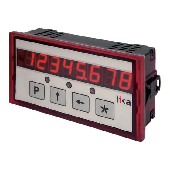
LD200
• Position display, counter, event transmitter, converter
• For HTL/Push-Pull, TTL/Line Driver, Sine/Cosine 1Vpp incremental
encoders/sensors and SSI absolute encoders/sensors
• Linear (mm, inches,...) and angular (degrees) display function
• 1 input and 3 dedicated digital outputs
• RS-232 interface and software tool for easy configuration
Suitable for the following models:
LD200 universal display
•
Lika Electronic
User's guide
•
Tel. +39 0445 806600
General Contents
Preliminary information
1 - Safety summary
2 - Identification
3 - Mounting instructions
4 - Electrical connections
5 - Functions
6 - Setup
7 - RS-232 serial interface
8 - Application software for PC
•
info@lika.biz
10
11
13
14
16
19
25
53
65
•
www.lika.biz
Advertisement
Table of Contents

Related Manuals for Lika LD200


Summary of Contents for Lika LD200
- Page 1 • 1 input and 3 dedicated digital outputs • RS-232 interface and software tool for easy configuration Suitable for the following models: General Contents Preliminary information LD200 universal display • 1 - Safety summary 2 - Identification 3 - Mounting instructions...
- Page 2 Tous droits réservés. This document and information contained herein are the property of Lika Electronic s.r.l. and shall not be reproduced in whole or in part without prior written approval of Lika Electronic s.r.l. Translation, reproduction and total or partial modification (photostat copies, film and microfilm included and any other means) are forbidden without written authorisation of Lika Electronic s.r.l.
-
Page 3: Table Of Contents
General contents User's guide................................. 1 General contents.....................................3 Subject index.....................................8 Typographic and iconographic conventions........................9 Preliminary information................................10 1 - Safety summary..................................11 1.1 Safety......................................11 1.2 Electrical safety..................................11 1.3 Mechanical safety................................12 2 - Identification..................................13 3 - Mounting instructions..............................14 3.1 Overall dimensions................................14 3.2 Installation.....................................15 3.3 Cleaning and maintenance.............................15 4 - Electrical connections...............................16 4.1 CON6 connections (Power supply to the display)....................16 4.2 CON1 connections (Mini-DIN connector).........................16... - Page 4 Unit......................................34 dir........................................34 dEciMALS....................................34 PrESEt......................................35 LIMIt P.......................................35 LIMIt N.......................................35 OFFSEt......................................35 EnAb. In.....................................36 6.6.1 Connecting an SSI encoder with “MSB Left Aligned” protocol............36 6.7 Lika's SM2, SM25, SM5 magnetic sensors........................40 Pitch......................................40 rES........................................40 Unit......................................40 dir........................................40 PrESEt......................................40 LIMIt P.......................................41 LIMIt N.......................................41 OFFSEt......................................41 EnAb. In.....................................41...
- Page 5 6.8 AB0 incremental linear encoder/sensor........................43 rES........................................43 Unit......................................43 EnAbLE 0....................................43 dir........................................43 PrESEt......................................44 LIMIt P.......................................44 LIMIt N.......................................44 OFFSEt......................................44 EnAb. In.....................................44 6.9 1Vpp Sine/Cosine linear encoder/sensor........................46 Pitch......................................46 rES........................................46 Unit......................................46 EnAbLE 0....................................46 dir........................................47 PrESEt......................................47 LIMIt P.......................................47 LIMIt N.......................................47 OFFSEt......................................47 EnAb. In.....................................48 6.10 Absolute linear encoder/sensor with SSI interface....................49 ForMAt.......................................49 StEPS......................................49 rES........................................50...
- Page 6 TFOR....................................57 RFOR....................................57 TPPR....................................57 RPPR....................................57 TREV....................................57 RREV....................................57 TDST....................................57 RDST....................................57 T360....................................57 R360....................................57 TSTE....................................57 RSTE....................................57 TPIT.....................................58 RPIT.....................................58 TRES....................................58 RRES....................................58 TPRO....................................58 RPRO....................................58 TCOD....................................59 RCOD....................................59 TUNI....................................59 RUNI....................................59 TETZ....................................59 RETZ....................................59 TDIR....................................59 RDIR....................................59 TDEC....................................60 RDEC....................................60 TREF....................................60 RREF....................................60 TLIP.....................................60 RLIP.....................................60 TLIM....................................60 RLIM....................................60 TOFF....................................60 ROFF....................................60 TEIN....................................60 REIN....................................60 TADR....................................61 RADR....................................61 TRLA....................................61 RRLA....................................61 TVER....................................61...
- Page 7 Setting the Pulses per revolution........................63 Reading the position of the decimal separator...................63 Reading the current position..........................63 Zero setting the position value..........................64 Starting the cyclic transmission.........................64 Reading the current position cyclically......................64 Stopping the cyclic transmission........................64 8 - Application software for PC............................65 8.1 Serial communication settings............................65 8.2 Selecting the encoder type.............................66 8.3 Reading the encoder parameters..........................67...
- Page 8 Subject index Ad....................26 MOd 360...............27, 30 codE................34, 50 n_turnS................33 d_tyPE...................26 OFFSEt........29, 32, 35, 41, 44, 47, 51 dEciMALS..............28, 31, 34 dir..........28, 31, 34, 40, 43, 47, 50 Pitch................40, 46 diSt_r..............27, 30, 33 PPr................27, 30, 33 PrESEt........28, 31, 35, 40, 44, 47, 50 EnAb.
-
Page 9: Typographic And Iconographic Conventions
Typographic and iconographic conventions In this guide, to make it easier to understand and read the text the following typographic and iconographic conventions are used: parameters and objects both of the device and the interface are coloured in GREEN; • alarms are coloured in RED;... -
Page 10: Preliminary Information
LD200 universal display. LD200 is a position display which allows to connect a variety of encoders / sensors, they can be incremental (HTL/Push-Pull, TTL/Line Driver, Sine/Cosine 1Vpp) and absolute (SSI) as well as rotary and linear. -
Page 11: Safety Summary
failure to comply with these precautions or with specific warnings elsewhere in this manual violates safety standards of design, manufacture, and intended use of the equipment; Lika Electronic assumes no liability for the customer's failure to comply with these requirements. 1.2 Electrical safety ... -
Page 12: Mechanical Safety
do not tool the unit; delicate electronic equipment: handle with care; do not subject the device to knocks or shocks; respect the environmental characteristics of the device. MAN LD200 E 2.3.odt 1 - Safety summary 12 of 72... -
Page 13: Identification
Information is listed in the delivery document too. Please always quote the order code and the serial number when reaching Lika Electronic for purchasing spare parts or needing assistance. For any information on the technical characteristics of the product, refer to the technical catalogue. -
Page 14: Mounting Instructions
H mm / 3.523” W x 1.732” H) made in the panel. Mount the panel clips on the sides of the display housing and tighten the screws until fixed. Values are expressed in millimeters MAN LD200 E 2.3.odt 3 - Mounting instructions 14 of 72... -
Page 15: Installation
(if necessary). Unauthorized opening and repair operations can have negative effects or cause failures to the protection measures of the unit. MAN LD200 E 2.3.odt 3 - Mounting instructions 15 of 72... -
Page 16: Electrical Connections
P.E. (GND) P.E. (GND) 4.2 CON1 connections (Mini-DIN connector) Plug the Mini-DIN circular connector of Lika's SM2, SM25 or SM5 sensors on the backside of the display. For more information refer to the technical documentation of the magnetic sensors. 4.3 CON2 connections (RS-232 serial interface) -
Page 17: Con3 Connections (Sine/Cosine 1Vpp)
See the “5.9 Zero setting (or Preset setting)” section on page EnAbLE 0 21. To enable it set the parameter in the specific menu to “ON”, the counting is zero set at the rising edge of the Zero signal. MAN LD200 E 2.3.odt 4 - Electrical connections 17 of 72... -
Page 18: Jumper J1 (Power Supply To The Encoder / Sensor)
Preset Input function (CON4, pins 7 and 8)” section on page 22 and in the “5.11 OUT 1, OUT 2, OUT 3 output function (CON4, pins 1 … 6)” section on page 23. MAN LD200 E 2.3.odt 4 - Electrical connections... -
Page 19: Functions
See the “5.5 Absolute / relative counting mode” section on page 20 LED 3 Description no function NOTE During initialisation, system checks the diagnostic LEDs for proper operation; therefore they light up for a while. MAN LD200 E 2.3.odt 5 - Functions 19 of 72... -
Page 20: Function Of The Keys
After reset you will have to repeat your individual set-up procedure. NOTE When you need to connect a new device to LD200 please upload the default parameters of the display before configuring it. 5.5 Absolute / relative counting mode... -
Page 21: Memory On Power Down (For Incremental And 1Vpp Encoders / Sensors)
("donE" will be displayed); via Preset digital input: see the “5.10 Preset Input function (CON4, pins 7 and 8)” section in the following page; MAN LD200 E 2.3.odt 5 - Functions 21 of 72... - Page 22 Refer to the parameter in the specific menus to enable this function. PrESEt Display value = 0 + value WARNING Input with optocoupler, Vin max = 30Vdc. Recommended wiring diagrams: MAN LD200 E 2.3.odt 5 - Functions 22 of 72...
-
Page 23: Examples Of Using The Input
HIGH LEVEL if the current position is < LIMIt N OUT 2 LOW LEVEL if the current position is > LIMIt N HIGH LEVEL while the reset command is active OUT 3 LOW LEVEL during normal operation MAN LD200 E 2.3.odt 5 - Functions 23 of 72... -
Page 24: Examples Of Using The Outputs
When we use the display zero setting function by means of the zero setting key or by sending the zero setting serial command (see on page 21), we contemporaneously transmit to the SSI encoder a 24V signal having a duration of 100 ms. MAN LD200 E 2.3.odt 5 - Functions 24 of 72... -
Page 25: Setup
To exit the SETUP procedure scroll the whole list of parameters by pressing P key. NOTE In the LD200 page of Lika's web site www.lika.biz an application software LD200_Serial_Communication_x_x.exe is available for parameter setup via RS-232 interface (CON2 connections). Please refer to the “7 - RS-232 serial interface”... -
Page 26: Basic Settings
Refer to “6.6 Absolute rotary encoder with SSI interface” section on on page 33 SM2, SM25, SM5 magnetic linear sensors M_SEnS Refer to “6.7 Lika's SM2, SM25, SM5 magnetic sensors” section on on page 40 AB0 incremental linear encoder/sensor M_Incr Refer to “6.8 AB0 incremental linear encoder/sensor”... -
Page 27: Ab0 Incremental Rotary Encoder
EnAbLE 0 is set to “On”, the display value is zero set at the rising edge of the Zero signal. OFF = Zero signal not enabled On = Zero signal enabled MAN LD200 E 2.3.odt 6 - Setup 27 of 72... -
Page 28: Decimals
This parameter is always expressed and calculated in metric measurement unit (millimeters). See also the “5.11 OUT 1, OUT 2, OUT 3 output function (CON4, pins 1 … 6)” section on page 23. MAN LD200 E 2.3.odt 6 - Setup 28 of 72... -
Page 29: Offset
PrESEt = 100 (encoder feature) diSt_r = 100 LIMIt P MOd 360 LIMIt N = OFF Unit OFFSEt = U_dec EnAbLE 0 = OFF EnAb. In = OFF = Up MAN LD200 E 2.3.odt 6 - Setup 29 of 72... -
Page 30: Vpp Sine/Cosine Rotary Encoder
EnAbLE 0 is set to “On”, the display value is zero set at the rising edge of the Zero signal. OFF = Zero signal not enabled On = Zero signal enabled MAN LD200 E 2.3.odt 6 - Setup 30 of 72... -
Page 31: Decimals
This parameter is always expressed and calculated in metric measurement unit (millimeters). See also the “5.11 OUT 1, OUT 2, OUT 3 output function (CON4, pins 1 … 6)” section on page 23. MAN LD200 E 2.3.odt 6 - Setup 31 of 72... -
Page 32: Offset
= 1024 (encoder feature) diSt_r LIMIt P = 36000 = 35998 MOd 360 LIMIt N = ON Unit OFFSEt = U_dec EnAbLE 0 = OFF EnAb. In = OFF = Up MAN LD200 E 2.3.odt 6 - Setup 32 of 72... -
Page 33: Absolute Rotary Encoder With Ssi Interface
Display value per turn [1, 99999999] (def: 4096) Value to be displayed after 1 revolution of the encoder. diSt_r is > PPr, a “jump” in the display value will occur. MAN LD200 E 2.3.odt 6 - Setup 33 of 72... -
Page 34: Prtcl
Encoder output code [GrAy, bin] (def: GrAy) Output code of the encoder. GrAy = Gray code (eg. Lika order code "GS" or "GR") bin = Binary code (eg. Lika order code "BS" or "BR") Unit Unit of measurement [U_dEc, Inch, Inch_F] (def: U_dEc) It sets the unit of measurement of the display mode to millimeters, inches or fractional inches. -
Page 35: Preset
key. This parameter is always expressed and calculated in metric measurement unit (millimeters). See also the “5.7 Offset” section on page 21. OFFSEt Position = current position + value MAN LD200 E 2.3.odt 6 - Setup 35 of 72... -
Page 36: Enab. In
= OFF 6.6.1 Connecting an SSI encoder with “MSB Left Aligned” protocol You can set the LD200 display for connection to a rotary or linear encoder equipped with “MSB Left Aligned” SSI serial protocol having a max. resolution of 25 bits. - Page 37 = the same as PPr, see the table below = 13-25 Prtcl = see the table below = Tree Number of bits n_turnS diSt_r 4096 4096 2048 2048 1024 1024 MAN LD200 E 2.3.odt 6 - Setup 37 of 72...
- Page 38 (resolution from 1 µm to 50 µm, Gray or binary code and “MSB Left Aligned” protocol). Please consider that the maximum measuring length of the SMA2 encoder over the MTA2 tape is 8,160 mm. MAN LD200 E 2.3.odt 6 - Setup 38 of 72...
- Page 39 8,160 Maximum number of information = = 8,160,000 0.001 8,160,000 = 2 Thus: n_turnS = 4,096 = 2 – 2 = 2,048, as you can see in the table above. MAN LD200 E 2.3.odt 6 - Setup 39 of 72...
-
Page 40: Lika's Sm2, Sm25, Sm5 Magnetic Sensors
LD200 6.7 Lika's SM2, SM25, SM5 magnetic sensors d_tyPE = M_SEnS. List of parameters of Lika's SM2, SM25 or SM5 series magnetic sensors with Mini-DIN connector. For connection refer to the “4.2 CON1 connections (Mini-DIN connector)” section on page 16. -
Page 41: Offset
If it is set to “On”, the Preset digital input can be used to activate the Preset function (see the “5.10 Preset Input function (CON4, pins 7 and 8)” section on page 22). OFF = Input not enabled On = Input enabled MAN LD200 E 2.3.odt 6 - Setup 41 of 72... - Page 42 LD200 EXAMPLE An SM5-R-2 sensor is connected to an LD200 display and has to display positions with a resolution of 0.01 mm, a tool correction factor of 5 mm and software limit switches at 0 and 1.5 meter. d_tyPE PrESEt...
-
Page 43: Ab0 Incremental Linear Encoder/Sensor
It sets the counting direction of the display value. uP = standard counting direction = count up when the sensor moves over the tape in the standard direction as explained in the manual dn = inverted counting direction MAN LD200 E 2.3.odt 6 - Setup 43 of 72... -
Page 44: Preset
If it is set to “On”, the Preset digital input can be used to activate the Preset function (see the “5.10 Preset Input function (CON4, pins 7 and 8)” section on page 22). OFF = Input not enabled On = Input enabled MAN LD200 E 2.3.odt 6 - Setup 44 of 72... - Page 45 MT50 tape have to be displayed. d_tyPE PrESEt = M_Incr LIMIt P = 0.01 mm Unit LIMIt N = U_dec EnAbLE 0 OFFSEt = OFF EnAb. In = Up = OFF MAN LD200 E 2.3.odt 6 - Setup 45 of 72...
-
Page 46: Vpp Sine/Cosine Linear Encoder/Sensor
“On”, the display value is zero set at the rising edge of the Zero signal. We recommend sensors with “R” Reference order code to be used. OFF = Zero signal not enabled On = Zero signal enabled MAN LD200 E 2.3.odt 6 - Setup 46 of 72... -
Page 47: Preset
key. This parameter is always expressed and calculated in metric measurement unit (millimeters). See also the “5.7 Offset” section on page 21. OFFSEt Position = current position + value MAN LD200 E 2.3.odt 6 - Setup 47 of 72... -
Page 48: Enab. In
= M_1VPP Pitch LIMIt P = 10 (1 mm, sensor feature) LIMIt N = 0.01 mm Unit OFFSEt = U_dec EnAbLE 0 EnAb. In = OFF = OFF = Up MAN LD200 E 2.3.odt 6 - Setup 48 of 72... -
Page 49: Absolute Linear Encoder/Sensor With Ssi Interface
SMA1 linear encoder over the MTA1 tape is 5,015 mm (see the technical sheet of the tape). So the encoder will provide the following maximum number of information: 5,015 Maximum number of information = = 1,003,000 0.005 MAN LD200 E 2.3.odt 6 - Setup 49 of 72... -
Page 50: Code
This function is useful, for example, when we want to pair the zero position of the application with the zero value that is displayed. To execute the preset see the “5.9 Zero setting (or MAN LD200 E 2.3.odt 6 - Setup 50 of 72... -
Page 51: Offset
If it is set to “On”, the Preset digital input can be used to activate the Preset function (see the “5.10 Preset Input function (CON4, pins 7 and 8)” section on page 22). OFF = Input not enabled On = Input enabled MAN LD200 E 2.3.odt 6 - Setup 51 of 72... - Page 52 LD200 EXAMPLE Display of the value measured by a Lika's absolute magnetic sensor, type SMA5- GA-10-L2. d_tyPE = M_SSI_ = Up ForMAt PrESEt = 13-25 StEPS LIMIt P = 524288 (2 LIMIt N = 0.01 mm codE OFFSEt = Gray (sensor feature) Unit EnAb.
-
Page 53: Rs-232 Serial Interface
WARNING Please make sure that RxD on PC side is connected to TxD on LD200 side and TxD on PC side is connected to RxD on LD200 side. 7.2 Setting the serial port Configure the serial port of the PC as shown in the following table:... -
Page 54: Protocol Structure
(see the “7.3.2 Commands” section on page 55 for available values). Acknowledge The acknowledge character confirms the correct transmission of data. PC LD200: ACK =“Null” (00 Hex) LD200 PC: ACK =“:” (3A Hex) Other values mean incorrect transmission. -
Page 55: Commands
EOF = “ ” (ASCII) = 04 (hex) 7.3.2 Commands Transmitted commands have the following meaning: “T…” (transmit): it means a command sent from the PC to the LD200 to • read a parameter value. DATA content has no meaning in this case LD200 replies sending back the same CMD, ACK = ”:”... -
Page 56: Tpos
E_1VPP (see on page 30) E_SSI_ (see on page 33) See an example of setting the device type in the “Setting the Device type” section on page 63. MAN LD200 E 2.3.odt 7 - RS-232 serial interface 56 of 72... -
Page 57: Tfor
DATA bytes 7-9 = 00 (Hex) DATA byte 10 (Hex) MOd 360 TSTE RSTE Number of steps [signed int 32 bit]. See the StEPS parameter on page 49. MAN LD200 E 2.3.odt 7 - RS-232 serial interface 57 of 72... -
Page 58: Tpit
0.05 0.25 0.25 TPRO RPRO Prtcl SSI protocol [bool]. See the parameter on page 34. DATA bytes 7-9 = 00 (Hex) DATA byte 10 (Hex) Prtcl Tree Shift MAN LD200 E 2.3.odt 7 - RS-232 serial interface 58 of 72... -
Page 59: Tcod
Counting direction [bool]. See the parameter in the specific menus. Possible values of DATA bytes are: DATA bytes 7-9 = 00 (Hex) DATA byte 10 (Hex) standard inverted MAN LD200 E 2.3.odt 7 - RS-232 serial interface 59 of 72... -
Page 60: Tdec
Enabling the Preset input [bool]. See the parameter in the specific menus. Possible values of DATA bytes are: DATA bytes 7-9 = 00 (Hex) DATA byte 10 (Hex) EnAb. In MAN LD200 E 2.3.odt 7 - RS-232 serial interface 60 of 72... -
Page 61: Tadr
21. DATA bytes are negligible. See an example of zero setting the display position in the “Zero setting the position value” section on page 64. MAN LD200 E 2.3.odt 7 - RS-232 serial interface 61 of 72... -
Page 62: Star
See an example of starting the cyclic transmission of the position value in the “Starting the cyclic transmission” section on page 64. See an example of cyclic transmission of the position value from LD200 in the “Reading the current position cyclically” section on page 64. -
Page 63: Examples Of Using The Protocol And The Commands
LD200 7.3.3 Examples of using the protocol and the commands In all examples the address of the device is 0 (ADD of LD200 = 0). Setting the Device type E_Incr = 04 h PC LD200 CMD = RDEV SOF ADD... -
Page 64: Zero Setting The Position Value
DATA = 00 00 03 E8 h => Position = 1000 Stopping the cyclic transmission PC LD200 CMD = STOP SOF ADD DATA 53544F50 0000 01C2 LD200 PC SOF ADD DATA 53544F50 0000 01FC MAN LD200 E 2.3.odt 7 - RS-232 serial interface 64 of 72... -
Page 65: Application Software For Pc
LD200_Serial_Communication_x_x.exe where _x_x is the release version of the file. The program is available for download at the page dedicated to LD200 in Lika's web site www.lika.biz. The program is designed to be installed simply by copying the executable file (*.exe file) to the desired location and there is no installation process. -
Page 66: Selecting The Encoder Type
Press the READ button next to the Address drop-down box to read the address that is set currently. Select a different address in the drop-down box and press the SET button to confirm a new address. MAN LD200 E 2.3.odt 8 - Application software for PC 66 of 72... -
Page 67: Reading The Encoder Parameters
LD200 If the PC communicates properly with LD200 the complete list of parameters for the the selected type of encoder is displayed. In case of wrong communication an error messages is displayed. The number of the COM port and the address of the encoder must be checked. -
Page 68: Reading The Position
(also a message appears in the Note field at the top of the page). Press the STOP button to stop the reading cycle. MAN LD200 E 2.3.odt 8 - Application software for PC 68 of 72... - Page 69 This page intentionally left blank...
- Page 70 This page intentionally left blank...
- Page 71 This page intentionally left blank...
- Page 72 “5.11 OUT 1, OUT 2, OUT 3 output function (CON4, pins 1 … 6)” 25.11.2009 updated 14.10.2010 SW update, general review 10.12.2018 General review, Italian and English versions separated Lika Electronic Via S. Lorenzo, 25 • 36010 Carrè (VI) • Italy Tel. +39 0445 806600 Fax +39 0445 806699 info@lika.biz...
Need help?
Do you have a question about the LD200 and is the answer not in the manual?
Questions and answers