Table of Contents
Advertisement
Quick Links
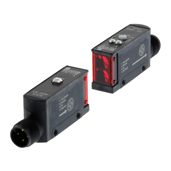
Built-in Amplifier Photoelectric Sensor (Medium Size)
E3S-A
Be sure to read Safety Precautions
on page 10.
Ordering Information
Built-in Amplifier Photoelectric Sensors
Sensing method
Through-beam
Sensors
Retro-reflective
Sensors
Downloaded from
Elcodis.com
electronic components distributor
Connection
Appearance
method
Pre-wired
Horizontal
Connector
(M12)
Pre-wired
Vertical
Connector
(M12)
Pre-wired
Horizontal
Connector
(M12)
Pre-wired
Vertical
Connector
(M12)
http://www.ia.omron.com/
Sensing distance
Functions
---
Timer
Self Diagnosis
---
7 m
---
Timer
Self Diagnosis
---
---
Timer
Self Diagnosis
---
2 m
---
(100 mm)
*1
Timer
Self Diagnosis
---
(c)Copyright OMRON Corporation 2008 All Rights Reserved.
Red light
Model
NPN output
PNP output
E3S-AT11
E3S-AT31
Turbo
E3S-AT21
E3S-AT41
External
Diagnosis
E3S-AT16
E3S-AT36
E3S-AT61
E3S-AT81
Turbo
E3S-AT71
E3S-AT91
External
Diagnosis
E3S-AT66
E3S-AT86
E3S-AR11
E3S-AR31
Turbo
E3S-AR21
E3S-AR41
External
Diagnosis
E3S-AR16
E3S-AR36
E3S-AR61
E3S-AR81
Turbo
E3S-AR71
E3S-AR91
External
Diagnosis
E3S-AR66
E3S-AR86
Infrared light
1
Advertisement
Table of Contents

Related Manuals for Omron E3S-A


Summary of Contents for Omron E3S-A
- Page 1 Self Diagnosis Diagnosis Connector E3S-AR16 E3S-AR36 (M12) Retro-reflective Sensors E3S-AR61 E3S-AR81 (100 mm) Pre-wired Vertical Timer Turbo E3S-AR71 E3S-AR91 External Self Diagnosis Diagnosis Connector E3S-AR66 E3S-AR86 (M12) http://www.ia.omron.com/ (c)Copyright OMRON Corporation 2008 All Rights Reserved. Downloaded from Elcodis.com electronic components distributor...
- Page 2 Note: When using any Reflector other than the provided one, use a sensing distance of approximately 0.7 times the typical value as a guide. * Values in brackets are the minimum required distance between the Sensor and Reflector. http://www.ia.omron.com/ (c)Copyright OMRON Corporation 2008 All Rights Reserved. Downloaded from Elcodis.com...
- Page 3 Sensors I/O Connectors Model Quantity Remarks E39-G2 Provided with product. Sensors I/O Connectors Cable Appearance Cable type Model XS2F-D421-DC0-A Straight XS2F-D421-GC0-A Standard 3-wire XS2F-D422-DC0-A L-shaped XS2F-D422-GC0-A http://www.ia.omron.com/ (c)Copyright OMRON Corporation 2008 All Rights Reserved. Downloaded from Elcodis.com electronic components distributor...
-
Page 4: Ratings And Specifications
(only for Sensors with connectors), and Reflector (only for Retro-reflective Sensors) *1. Values in brackets are the minimum required distance between the Sensor and Reflector. *2. National Electrical Manufacturers Association http://www.ia.omron.com/ (c)Copyright OMRON Corporation 2008 All Rights Reserved. Downloaded from Elcodis.com electronic components distributor... -
Page 5: Engineering Data (Typical)
E39-R1 Reflector Oper- ating level Oper- ating 0 0.2 0.4 0.6 0.8 1 1.2 1.4 1.6 1.8 2 2.2 2.4 2.6 level Distance (m) Distance (m) http://www.ia.omron.com/ (c)Copyright OMRON Corporation 2008 All Rights Reserved. Downloaded from Elcodis.com electronic components distributor... -
Page 6: I/O Circuit Diagrams
Power E3S-AD67 indica- E3S-AD13 Photo- 10 to (red) electric 30 VDC E3S-AD18 Sensor main E3S-AD63 circuit Blue Note: Pins 2 and 4 are not used. E3S-AD68 http://www.ia.omron.com/ (c)Copyright OMRON Corporation 2008 All Rights Reserved. Downloaded from Elcodis.com electronic components distributor... - Page 7 Classification Wire color Connection Pin No. Application Terminal No. Brown Brown For DC Blue Blue Black Black Output XS2F-D421-DC0-A Note: Pin No. 2 is not used. http://www.ia.omron.com/ (c)Copyright OMRON Corporation 2008 All Rights Reserved. Downloaded from Elcodis.com electronic components distributor...
- Page 8 10 to 30 VDC External (red) diagnostic (External input diagnostic input) (Between brown and pink) Photo- Emitter LED electric Sensor main Indicator Pink circuit (red) Blue http://www.ia.omron.com/ (c)Copyright OMRON Corporation 2008 All Rights Reserved. Downloaded from Elcodis.com electronic components distributor...
-
Page 9: Adjustment Methods
Unlike conventional Photoelectric Sensors, the variation in the sensitivity of E3S-A Photoelectric Sensors is minimal. This means the sensitivity can be adjusted on only a single Photoelectric Sensor, and then the adjusters on the other Photoelectric Sensors can be set to the same scale position. -
Page 10: Safety Precautions
The direction of the optical axis coincides with the machine Do not use it for such purposes. axis of the E3S-A when the mounting screw is inserted into the lock hole of the Mounting Bracket. If the mounting surface and the screw hole are correctly aligned toward the sensing... - Page 11 Receiver connector is located. Using the E39-R5 Optical Axis Reflector for Through- With this operating mode selector, the E3S-A is in either Dark- beam Sensors ON or Light-ON mode. (Accessory, order Separately)
- Page 12 *The Mounting Bracket can be attached to side A. Insulator diameter: 1.1 mm), 12.9 12.5 Standard length: 2 m E3S-AT21/41(Emitter) 8.8 dia. 12.4 Optical 10.5 axis Mounting Holes 28.9 16.9 Two, M3 holes 10.5 http://www.ia.omron.com/ (c)Copyright OMRON Corporation 2008 All Rights Reserved. Downloaded from Elcodis.com electronic components distributor...
- Page 13 Two, M3 × 12 screws 29.2 Mounting Holes Two, M3 1.2 10.7 Two, M3 × 12 screws *The Mounting Bracket can be attached to side A. http://www.ia.omron.com/ (c)Copyright OMRON Corporation 2008 All Rights Reserved. Downloaded from Elcodis.com electronic components distributor...
- Page 14 Turbo switch 12.5 29.2 1.2 10.7 *The E3S-AT71 of E3S-AT91 Mounting Holes has three conductors. Two, M3 holes *The Mounting Bracket can be attached to side A. http://www.ia.omron.com/ (c)Copyright OMRON Corporation 2008 All Rights Reserved. Downloaded from Elcodis.com electronic components distributor...
- Page 15 Two, M3 × 12 screws E39-L60 Close Mounting Plate (provided) (Attach the mounting plate or the plug cannot be connected.) *The Mounting Bracket can be attached to side A. http://www.ia.omron.com/ (c)Copyright OMRON Corporation 2008 All Rights Reserved. Downloaded from Elcodis.com electronic components distributor...
- Page 16 Two, M3 × 12 screws Emitter 29.2 Mounting Holes 1.2 10.7 Two, M3 holes Two, M3 × 12 screws *The Mounting Bracket can be attached to side A. http://www.ia.omron.com/ (c)Copyright OMRON Corporation 2008 All Rights Reserved. Downloaded from Elcodis.com electronic components distributor...
- Page 17 Two, M3 × 12 screws 10.5 E39-L60 Close Mounting Plate (provided) (Attach the mounting plate or the plug cannot be connected.) *The Mounting Bracket can be attached to side A. http://www.ia.omron.com/ (c)Copyright OMRON Corporation 2008 All Rights Reserved. Downloaded from Elcodis.com electronic components distributor...
- Page 18 Two, M3 × 12 screws Emitter 1.2 10.7 Mounting Holes Two, M3 holes Two, M3 × 12 screws *The Mounting Bracket can be attached to side A. http://www.ia.omron.com/ (c)Copyright OMRON Corporation 2008 All Rights Reserved. Downloaded from Elcodis.com electronic components distributor...
- Page 19 Two, M3 × 12 screws E39-L60 Close Mounting Plate (provided) (Attach the mounting plate or the plug cannot be connected.) *The Mounting Bracket can be attached to side A. http://www.ia.omron.com/ (c)Copyright OMRON Corporation 2008 All Rights Reserved. Downloaded from Elcodis.com electronic components distributor...
- Page 20 Emitter panel of E3S-A 11.6 11.2 59.9 Material: Reflector: Acryl Back: ABS 40.9 In the interest of product improvement, specifications are subject to change without notice. http://www.ia.omron.com/ (c)Copyright OMRON Corporation 2008 All Rights Reserved. Downloaded from Elcodis.com electronic components distributor...
-
Page 21: General Precautions
(2) Do not use the Sensor in environments where the cables may become immersed in oil or other liquids or where liquids may penetrate the Sensor. Doing so may result in damage from burning and fire, particularly if the liquid is flammable. http://www.ia.omron.com/ (c)Copyright OMRON Corporation 2008 All Rights Reserved. Downloaded from Elcodis.com... - Page 22 (Light may enter even if the Sensors are separated by Sensor Sensor more than the sensing distance.) θ θ Adjust the Lowering the sensitivity will generally help. sensitivity. http://www.ia.omron.com/ (c)Copyright OMRON Corporation 2008 All Rights Reserved. Downloaded from Elcodis.com electronic components distributor...
- Page 23 Repeated Bending other terminals. Normally, the Sensor cable should not be bent repeatedly. (For bending-resistant cable, see Attachment to Moving Parts page C-4.) http://www.ia.omron.com/ (c)Copyright OMRON Corporation 2008 All Rights Reserved. Downloaded from Elcodis.com electronic components distributor...
- Page 24 The testing conditions of the standard cable and robot cable are different. Refer to the values in the above table to check bend-resistant performance under actual working conditions. http://www.ia.omron.com/ (c)Copyright OMRON Corporation 2008 All Rights Reserved. Downloaded from Elcodis.com electronic components distributor...
- Page 25 Note:1.To maintain the fiber characteristics, make sure that the lock is released before removing the fibers. 2. Lock and unlock the fibers at an ambient temperature of − 10 to 40°C. http://www.ia.omron.com/ (c)Copyright OMRON Corporation 2008 All Rights Reserved. Downloaded from Elcodis.com electronic components distributor...
- Page 26 Cleaning • Keep organic solvents away from the Sensor. Organic solvents will dissolve the surface. • Use a soft, dry cloth to clean the Sensor. http://www.ia.omron.com/ (c)Copyright OMRON Corporation 2008 All Rights Reserved. Downloaded from Elcodis.com electronic components distributor...
- Page 27 Warranty and Limitations of Liability WARRANTY OMRON's exclusive warranty is that the products are free from defects in materials and workmanship for a period of one year (or other period if specifi ed) from date of sale by OMRON. OMRON MAKES NO WARRANTY OR REPRESENTATION, EXPRESS OR IMPLIED, REGARDING NON-INFRINGEMENT, MERCHANTABILITY, OR FITNESS FOR PARTICULAR PURPOSE OF THE PRODUCTS.
Need help?
Do you have a question about the E3S-A and is the answer not in the manual?
Questions and answers