Advertisement
Quick Links
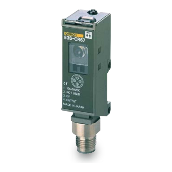
Transparent Bottle Sensor
E3S-CR62/67
Ideal for Detecting Transparent Glass
and Plastic Containers
■ Reliably detects narrow 5-mm gaps between bottles
(When using the E39-R6).
■ Significantly higher S/N ratio makes detection more
reliable for various transparent containers.
Be sure to read Safety Precautions on
page 5.
Ordering Information
Sensors
Sensing method
Appearance
Retro-reflective
* Values in parentheses indicate the minimum required distance between the Sensor and Reflector.
Accessories (Order Separately)
Reflectors
Name
250 mm
Reflectors
1 m [250 mm]
* Values in parentheses indicate the minimum required distance between the Sensor and Reflector.
Mounting Brackets
Appearance
Model
E39-L103
E39-L87
http://www.ia.omron.com/
Connection method
Pre-wired
Standard M12 Connector
Sensing distance
E39-R6
*
E39-R1
Quantity
1
Supplied with the product.
1
Sensing distance
Reflector E39-R6
250 mm
Model
Quantity
1
Supplied with the product.
1
Remarks
---
(c)Copyright OMRON Corporation 2007 All Rights Reserved.
Model
Reflector E39-R1
E3S-CR62
*
1 m
E3S-CR67
[250 mm]
Remarks
---
Red light
1
Advertisement

Related Manuals for Omron E3S-CR62


Summary of Contents for Omron E3S-CR62
- Page 1 Reflectors 1 m [250 mm] E39-R1 * Values in parentheses indicate the minimum required distance between the Sensor and Reflector. Mounting Brackets Appearance Model Quantity Remarks E39-L103 Supplied with the product. E39-L87 http://www.ia.omron.com/ (c)Copyright OMRON Corporation 2007 All Rights Reserved.
- Page 2 Brackets Accessories Clamps (with screws), Adjustment driver, Instruction manual, Reflective Plate *1. Values in parentheses indicate the minimum required distance between the Sensor and Reflector. *2. NEMA (National Electrical Manufacturers Association) Standard http://www.ia.omron.com/ (c)Copyright OMRON Corporation 2007 All Rights Reserved.
- Page 3 −10 −20 −20 −30 −30 E3S-CR62/67 + E39-R1 (Vertical Direction) (Horizontal Direction) E39-R1 E39-R1 Reflector Reflector Set distance X (m) Set distance −10 −10 X (m) −20 −20 −30 −30 −40 −40 http://www.ia.omron.com/ (c)Copyright OMRON Corporation 2007 All Rights Reserved.
- Page 4 Note: Pin 2 is not used. Nomenclature Light indicator (red) Stability indicator SENS (green) Output selector * Sensitivity adjuster Operation selector * * Use the output selector to select the type of output transistor, NPN or PNP. http://www.ia.omron.com/ (c)Copyright OMRON Corporation 2007 All Rights Reserved.
- Page 5 • When mounting the E3S-CR62/67, do not hit the E3S-CR62/67 with a hammer, or the E3S-CR62/67 will loose watertightness. • Use M4 screws to mount the E3S-CR62/67. The tightening torque Precautions for Correct Use of each screw must be 1.18 N·m maximum.
- Page 6 Light indicator (red) 11.5 20.2 32.2 (A)*1 M3 × 5 Two, M4 23.2 (31) * Mounting Bracket can be attached to side A. Accessories (Order Separately) Reflectors Sensor I/O Connectors Mounting Brackets http://www.ia.omron.com/ (c)Copyright OMRON Corporation 2007 All Rights Reserved.
- Page 7 Opaque object or no sensing size or smaller, turn the sensitivity control object Stability Light from minimum to maximum and set it at Min. Max. (green) (red) point where the incident light stabilizes. http://www.ia.omron.com/ (c)Copyright OMRON Corporation 2007 All Rights Reserved.
- Page 8 (2) Do not use the Sensor in environments where the cables may become immersed in oil or other liquids or where liquids may penetrate the Sensor. Doing so may result in damage from burning and fire, particularly if the liquid is flammable. http://www.ia.omron.com/ (c)Copyright OMRON Corporation 2007 All Rights Reserved.
- Page 9 Receiver. Sensor sensing distance.) (Light may enter even if the Sensors are separated by Sensor Sensor more than the sensing distance.) θ θ Adjust the Lowering the sensitivity will generally help. sensitivity. http://www.ia.omron.com/ (c)Copyright OMRON Corporation 2007 All Rights Reserved.
- Page 10 Repeated Bending other terminals. Normally, the Sensor cable should not be bent repeatedly. (For bending-resistant cable, see Attachment to Moving Parts page C-4.) http://www.ia.omron.com/ (c)Copyright OMRON Corporation 2007 All Rights Reserved.
- Page 11 Approx. 13,000 times Approx. 500,000 times The testing conditions of the standard cable and robot cable are different. Refer to the values in the above table to check bend-resistant performance under actual working conditions. http://www.ia.omron.com/ (c)Copyright OMRON Corporation 2007 All Rights Reserved.
- Page 12 Locked position Note:1.To maintain the fiber characteristics, make sure that the lock is released before removing the fibers. 2. Lock and unlock the fibers at an ambient temperature of − 10 to 40°C. http://www.ia.omron.com/ (c)Copyright OMRON Corporation 2007 All Rights Reserved.
- Page 13 (height) detection data, and selection list for specifications. Cleaning • Keep organic solvents away from the Sensor. Organic solvents will dissolve the surface. • Use a soft, dry cloth to clean the Sensor. http://www.ia.omron.com/ (c)Copyright OMRON Corporation 2007 All Rights Reserved.
- Page 14 Warranty and Limitations of Liability WARRANTY OMRON's exclusive warranty is that the products are free from defects in materials and workmanship for a period of one year (or other period if specifi ed) from date of sale by OMRON. OMRON MAKES NO WARRANTY OR REPRESENTATION, EXPRESS OR IMPLIED, REGARDING NON-INFRINGEMENT, MERCHANTABILITY, OR FITNESS FOR PARTICULAR PURPOSE OF THE PRODUCTS.
Need help?
Do you have a question about the E3S-CR62 and is the answer not in the manual?
Questions and answers