Advertisement
Quick Links
q
1. MAIN PWB . . . . . . . . . . . . . . . . . . . . . . . . . . . . . . . . . . . . . . . . . . . 1
CPU
ASIC
Memory
Driver (1)
Driver (2)
Driver (3)
Noise filter/Pull-up
Connector (1)
Connector (2)
2. LOW VOLTAGE POWER SUPPLY. . . . . . . . . . . . . . . . . . . . . . . . 10
100VAC (85 - 127V)
120VAC (102 - 140V)
220-240VAC (187 - 276V)
3. CCD PWB . . . . . . . . . . . . . . . . . . . . . . . . . . . . . . . . . . . . . . . . . . . 13
4. COPY OPE PWB. . . . . . . . . . . . . . . . . . . . . . . . . . . . . . . . . . . . . . 14
5. I/F PWB . . . . . . . . . . . . . . . . . . . . . . . . . . . . . . . . . . . . . . . . . . . . . 16
6. SCAN OPE PWB. . . . . . . . . . . . . . . . . . . . . . . . . . . . . . . . . . . . . . 17
7. TRAY PWB . . . . . . . . . . . . . . . . . . . . . . . . . . . . . . . . . . . . . . . . . . 18
Î g #
!
Ê
Ë
Parts marked with "!" are important for maintaining the safety of the set. Be sure to replace these parts with specified
ones for maintaining the safety and performance of the set.
A &
H
; e
k Î
CIRCUIT DIAGRAM
. . . . . . . . . . . . . . . . . . . . . . . . . . . . . . . . . . . . . . . . . . . . . . . . 1
. . . . . . . . . . . . . . . . . . . . . . . . . . . . . . . . . . . . . . . . . . . . . . . 2
. . . . . . . . . . . . . . . . . . . . . . . . . . . . . . . . . . . . . . . . . . . . . 3
. . . . . . . . . . . . . . . . . . . . . . . . . . . . . . . . . . . . . . . . . . . . 4
. . . . . . . . . . . . . . . . . . . . . . . . . . . . . . . . . . . . . . . . . . . . 5
. . . . . . . . . . . . . . . . . . . . . . . . . . . . . . . . . . . . . . . . . . . . 6
. . . . . . . . . . . . . . . . . . . . . . . . . . . . . . . . . . . . . . 7
. . . . . . . . . . . . . . . . . . . . . . . . . . . . . . . . . . . . . . . . . 8
. . . . . . . . . . . . . . . . . . . . . . . . . . . . . . . . . . . . . . . . . 9
. . . . . . . . . . . . . . . . . . . . . . . . . . . . . . . . . . . 10
. . . . . . . . . . . . . . . . . . . . . . . . . . . . . . . . . . . 11
Ê X + # $
' f
Ë $
SHARP CORPORATION
Ë
'
DIGITAL COPIER
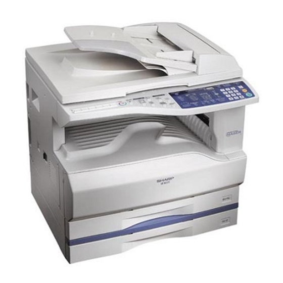
AR-200M
AR-160M
AR-M205
AR-M160
AR-5220
MODEL
CONTENTS
. . . . . . . . . . . . . . . . . . . . . . . . . . . . . . . 12
Ë
Ê
" :
CODE : 00Z
ARM205/C1/
Japan only
Japan only
Except Japan
Except Japan
Except Japan
# X
This document has been published to be used
for after sales service only.
The contents are subject to change without notice.
$
Advertisement

Related Manuals for Sharp AR-200M


Summary of Contents for Sharp AR-200M
- Page 1 CIRCUIT DIAGRAM CODE : 00Z ARM205/C1/ DIGITAL COPIER AR-200M Japan only AR-160M Japan only AR-M205 Except Japan AR-M160 Except Japan AR-5220 MODEL Except Japan CONTENTS 1. MAIN PWB ......... . . 1 .
- Page 2 AR-M205/M160/l5220 – 1 –...
- Page 3 AR-M205/M160/l5220 – 2 –...
- Page 4 AR-M205/M160/l5220 – 3 –...
- Page 5 AR-M205/M160/l5220 – 4 –...
- Page 6 AR-M205/M160/l5220 – 5 –...
- Page 7 AR-M205/M160/l5220 – 6 –...
- Page 8 AR-M205/M160/l5220 – 7 –...
- Page 9 AR-M205/M160/l5220 – 8 –...
- Page 10 AR-M205/M160/l5220 – 9 –...
- Page 11 AR-M205/M160/l5220 – 10 –...
- Page 12 AR-M205/M160/l5220 – 11 –...
- Page 13 AR-M205/M160/l5220 – 12 –...
- Page 14 AR-M205/M160/l5220 – 13 –...
- Page 15 AR-M205/M160/l5220 – 14 –...
- Page 16 AR-M205/M160/l5220 – 15 –...
- Page 17 AR-M205/M160/l5220 – 16 –...
- Page 18 AR-M205/M160/l5220 – 17 –...
- Page 19 AR-M205/M160/l5220 – 18 –...
- Page 20 COPYRIGHT 2003 BY SHARP CORPORATION All rights reserved. Printed in Japan. No part of this publication may be reproduced, stored in a retrieval system, or transmitted. In any form or by any means, electronic, mechanical, photocopying, recording, or otherwise, without prior written permission of the publisher.
- Page 21 外装 (Exteriors) 梱包材&付属品 (Packing material & Accessories) 操作部 (Operation panel section) 1ST トレイ外装 サイドドアーユニット (Side door unit) (1ST Tray exteriors)...AR-200M,AR-M205 光学ユニット (Optical unit) 1ST トレイ給紙ユニット 第 2.3 ミラーユニット (2nd,3rd mirror unit) (1ST Tray paper feeding unit) .......AR200M,AR-M205 中間フレームユニット (Middle frame unit) 索引...
- Page 22 F For U.S. only-Use order codes provided in advertising literature. Do not order from parts department. 外装 (Exteriors) PRICE RANK PART PARTS CODE DESCRIPTION MARK RANK 1 GCOVH0010QSE5 [AR-200M/AR-160M/AR-M160/AR-5220] OC カバー OC cover 2 PCUSS0023QSZZ [AR-200M/AR-160M/AR-M160/AR-5220] OC マット OC sheet 3 CHNG-0007QS02 [AR-200M/AR-160M/AR-M160/AR-5220] OC ヒンジ OC hinge 4 XEBSE40P10000 [AR-200M/AR-160M/AR-M160/AR-5220] ビス...
- Page 23 Class 1 label TLABZ0105RSZZ (LAG4) LAG 原産地ラベル LAG place origin label 59 TCAUH1047FCZZ (Poland only) サービス注意ラベル Service caution label 501 CCOVH0010RS56 [AR-200M,AR-160M,AR-M160,AR-5220] OC カバーユニット OC cover unit CFIX-0024RS52 (Japan only) テーブルユニット Table unit CFIX-0024RS51 (Other countries) テーブルユニット Table unit 外装 (Exteriors) PRP01597 –...
- Page 24 [AR-M160(Other Countries)/AR-5220] SIMP デコパネル SIMP Deco.panel 20 DHAI-0324QSZZ OP-MCU FFC ハーネス OP-MCU FFC harness 21 XEBSE30P08000 ビス Screw(3×8) (Unit) CCAB-0073RS58 [AR-200M] 操作パネルユニット Operation panel unit CCAB-0073RS52 [AR-M160(U.S.A only)] 操作パネルユニット Operation panel unit CCAB-0073RS53 [AR-M160(Canada only)] 操作パネルユニット Operation panel unit CCAB-0073RS59 [AR-M205(U.S.A only)] 操作パネルユニット...
- Page 25 操作部 (Operation panel section) 16 16 PRP01598 – 4 –...
- Page 26 PS upper roller 31 MSPRC0319QSZZ 右ドアーノブバネ Right door knob spring 32 JKNBZ0008QSZZ 右ドアーノブ Right door knob (Unit) サイドドアーユニット Side door unit(Without No.16,18) CDOR-0004RS51 [AR-200M/AR-160M/AR-M160/AR-5220] (No.16,18 除く ) [AR-M205] サイドドアーユニット Side door unit(Without No.16,18) CDOR-0004RS52 (No.16,18 除く ) – 5 –...
- Page 27 サイドドアーユニット (Side door unit) PRP01599 – 6 –...
- Page 28 光学ユニット (Optical unit) PRICE RANK PART PARTS CODE DESCRIPTION MARK RANK 1 PWIR-0006QSZZ MB ワイヤー F MB wire F 2 CMIR-0008QS35 第 2.3 ミラーユニット 2nd,3rd mirror unit 3 PWIR-0005QSZ1 MB ワイヤー R MB wire R 4 LHLDZ0109QSZZ ワイヤーホルダー Wire holder 5 XBPSD40P06K00 ビス...
- Page 29 光学ユニット (Optical unit) PRP01600 – 8 –...
- Page 30 第 2.3 ミラーユニット (2nd,3rd mirror unit) PRICE RANK PART PARTS CODE DESCRIPTION MARK RANK 1 LHLDZ0044QSZ2 第 2.3 ミラーホルダー 2nd,3rd mirror holder 3 XBPSD40P06KS0 ビス Screw(4×6KS) 4 NPLYZ0017QSZZ W プーリー W pulley 5 LHLDZ0013QSZZ CL ガイドホルダー CL guide holder 7 MSLI-0138FCZZ スライダー...
- Page 31 第 2.3 ミラーユニット (2nd,3rd mirror unit) PRP01601 中間フレームユニット (Middle frame unit) 31 39 PRP01602 – 10 –...
- Page 32 プロセスユニット (Process unit) PRICE RANK PART PARTS CODE DESCRIPTION MARK RANK 1 XEBSD30P10000 ビス Screw(3×10) 2 CHLDZ0035RS51 MC ホルダーユニット MC holder unit 3 UCLEZ0009QSZ1 クリーニングブレード Cleaning blade 4 CFRM-0021RS61 (Other Countries) プロセスサブユニット Process sub unit 5 PSEL-0130QSZZ モケット R Seal R 6 PSEL-0129QSZZ モケット...
- Page 33 現像カートリッジユニット (DV cartridge unit) PRICE RANK PART PARTS CODE DESCRIPTION MARK RANK 501 CBOX-0001JS5E DV box ユニット DV box unit 502 CCOVP0072RS53 DV カバーユニット DV cover unit 503 CGIDM0089RS51 TN ガイドユニット TN guide unit プロセスユニット (Process unit) 13 14 PRP01603 現像カートリッジユニット...
- Page 34 定着ユニット (Fusing unit) PRICE RANK PART PARTS CODE DESCRIPTION MARK RANK 1 XBPSD30P06KS0 ビス Screw(3×6KS) 2 RTHM-0001QSZZ サーモスタット Thermostat 3 DHAI-0184QSZ1 定着ハーネス Fusing harness 4 XHBSD30P06000 ビス Screw(3×6) 5 PCOVP0029QSZ3 定着カバー Fusing cover RLMPU0014QSZZ ヒーターランプ Heater lamp(100V series) RLMPU0018QSZZ ヒーターランプ Heater lamp(110V series) RLMPU0015QSZZ ヒーターランプ...
- Page 35 定着ユニット (Fusing unit) PRP01605 – 14 –...
- Page 36 501 CGERH0011RS51 MG ギヤーユニット MG gear unit CPLTM0047RS76 [AR-200M/AR-160M/AR-M160/AR-5220] 駆動サブユニット Driving sub unit CPLTM0047RS77 [AR-M205] 駆動サブユニット Driving sub unit (Unit) Driving unit(Without No.5) CPLTM0047RS56 [AR-200M/AR-160M/AR-M160/AR-5220] 駆動ユニット (No.5 除く ) CPLTM0047RS57 [AR-M205] 駆動ユニット (No.5 除く ) Driving unit(Without No.5) – 15 –...
- Page 37 メイン駆動ユニット (Main driving unit) PRP01606 – 16 –...
- Page 38 44 NGERH0078QSZZ 2ND 連結ギヤー Joint gear(39/33T) 45 NGERH1169FCZZ 2ND 連結ギヤー 2ND Joint gear 46 CPLTM0114QS01 2ND 連結ギヤ取付板 Joint gear fixing plate 48 LPLTM0112QSZZ [AR-200M/AR-M205] 接合板 Adjustment plate 49 XEBSE40P14000 [AR-200M/AR-M205] ビス Screw(4×14) 52 LPLTM0125QSZZ 目隠し板 Blind plate 55 PSPAZ0024QSZZ 2ND 連結スペーサー...
- Page 39 台板ユニット 1 (Base plate unit 1) PRP01607 台板ユニット 2 (Base plate unit 2) PRICE RANK PART PARTS CODE DESCRIPTION MARK RANK 1 LSOU-0036QSZZ 排紙トレイ Delivery tray 2 GCAB-0069QSZZ 排紙後カバー Delivery rear cover 3 XEBSE40P10000 ビス Screw(4×10) 5 CPWBF0114QSE3 GDI 基板 GDI PWB 6 NFANP0010QSZZ PS ファン...
- Page 40 六角ビス Screw 34 LANGT0014QSZZ MCU PWB 取付け板 MCU PWB fixing plate 35 LX-BZ0750FCZZ ビス Screw(3×6) 36 NBLTT0007QSZZ Delivery roller drive belt [AR-200M/AR-160M/AR-M160/AR-5220] 排紙ローラ駆動ベルト CPWBX0128QS34 [AR-200M] MCU 基板 MCU PWB CPWBX0128QS36 [AR-160M] MCU 基板 MCU PWB CPWBX0128QS31 [AR-M160] MCU 基板 MCU PWB CPWBX0128QS32 [AR-M205] MCU 基板...
- Page 41 台板ユニット 2 (Base plate unit 2) 13 66 PRP01608 – 20 –...
- Page 42 手差しマルチユニット (Manual paper feeding multi unit) PRICE RANK PART PARTS CODE DESCRIPTION MARK RANK 1 PCOVP0098QSZZ マルチフレームカバー Multi frame cover 2 MARMP0008QSZZ ストッパーアーム Stopper arm 3 LPLTP0056QSZ3 ストッパー板 Stopper plate 4 XRESP40-06000 E リング E type ring 5 LBOSZ1510FCZZ カムボス A1 Cam boss A1 6 PPIPP0109FCZZ 手差しクラッチスリーブ...
- Page 43 手差しマルチユニット (Manual paper feeding multi unit) PRP01609 – 22 –...
- Page 44 [AR-M205] DUP 排紙ローラー DUP delivery roller 39 LFRM-0027QSZ2 排紙フレ - ム Delivery frame PFILZ0004QSZZ [AR-160M/AR-M160/AR-M205/AR-5220] オゾンフィルター Ozone filter PFILZ0008QSZZ [AR-200M] オゾンフィルター 20 Ozone filter 20 41 PMLT-0027QSZZ ク - リングファンモルト Cleaning fan cushion 42 XEBSD20P06000 ビス Screw(2×6) 43 NFANP0009QSZZ ク - リングファン...
- Page 45 排紙フレームユニット (Delivery frame unit) 31 30 14 15 PRP01610 – 24 –...
- Page 46 TC ケースユニット (TC case unit) PRICE RANK PART PARTS CODE DESCRIPTION MARK RANK 1 XEBSE30P08000 ビス Screw(3×8) 2 PGIDH0118QSZZ TC 前ガイド TC front guide 3 PSHEP0050QSZ1 TC マイラー TC sheet 5 PSHEP0051QSZZ TC カバーマイラー F TC cover sheet F 6 LHLDZ0030QSZZ TC ホルダー...
- Page 47 250 枚トレイユニット (250 sheets tray unit) PRICE RANK PART PARTS CODE DESCRIPTION MARK RANK 1 LPLTM0053QSZ1 回転板 Rotation plate 2 PSHEZ0441QSZZ 回転板シート Rotation plate sheet 3 LHLDW1226FCZZ ターンファスナー Turn faster 4 LPLTM2642FCG2 カセツト後端板 Tray rear plate 7 XRESP40-06000 E リング E type ring 8 TLABH0064QSZ1 指示線ラベル...
- Page 48 Top packing cushion R 3 SPAKA0463QSZZ 天アド L Top packing cushion L 5 SSAKZ0003QSZZ ポリ袋 Vinyl bag 6 UBAGF0018YSZ1 [AR-200M/AR160M] DV アルミ袋 DV aluminum bag 7 SPAKA0134QSZZ [AR-200M/AR-160M/AR-M160/AR5220] OC 保護シート OC protect sheet 8 TCADZ0010QSZZ 固定ビス注意カード Fixer screw caution card 9 LX-BZ0015QSZZ 第...
- Page 49 梱包材&付属品 (Packing material & Accessories) PRP01613 – 28 –...
- Page 50 1ST トレイ外装 (1ST Tray exteriors)..AR-200M,AR-M205 PRICE RANK PART PARTS CODE DESCRIPTION MARK RANK 1 GCOV-0020QSE1 後カバー Rear cover 2 GGAD-0001QSZZ エッジガード 上 Edge guard upper 3 GGAD-0002QSZZ エッジガード 下 Edge guard lower 4 LSUPP0083FCZZ 基板サポーター Supporter(LCBS-3) 5 LPLTM0116QSZZ 連結板 R...
- Page 51 1ST トレイ外装 (1ST Tray exteriors)..AR-200M,AR-M205 PRP01614 – 30 –...
- Page 52 1ST トレイ給紙ユニット (1ST Tray paper feeding unit)..AR-200M,AR-M205 PRICE RANK PART PARTS CODE DESCRIPTION MARK RANK 1 NGERH1207FCZZ 連結ギヤー Joint gear(40T) 2 MARMP0229FCZZ 連結アーム Joint arm 3 MSPRT0128QSZZ 連結アームバネ Joint arm spring 4 XRESP50-06000 E リング E type ring 5 LBOSZ1031FCZZ クラッチボス...
- Page 53 1ST トレイ給紙ユニット (1ST Tray paper feeding unit)..AR-200M,AR-M205 PRP01615 – 32 –...
- Page 54 索引 (Index) PRICE R. JAPAN ONLY PARTS CODE NEW P/R ORDER CODE CPNLH0026QS13 PRICE R. JAPAN ONLY 578 158 0402 2- 17 PARTS CODE NEW P/R CPNLH0026QS15 ORDER CODE 578 158 0403 2- 17 CPNLH0026QS16 578 158 0404 2- 17 CARMP0010QS01 CPNLH0026QS18 578 158 0405...
- Page 55 PRICE R. PRICE R. JAPAN ONLY JAPAN ONLY PARTS CODE NEW P/R PARTS CODE NEW P/R ORDER CODE ORDER CODE GCOV-0020QSE1 LPFTF0004QSZZ 578 110 0241 AQ EQ 578 217 0006 4- 62 GCOV-0021QSE2 LPINS0181FCZZ 578 110 0242 18- 24 AP EQ 572 218 0093 19- 22 AA DD...
- Page 56 PRICE R. PRICE R. JAPAN ONLY JAPAN ONLY PARTS CODE NEW P/R PARTS CODE NEW P/R ORDER CODE ORDER CODE LX-WZ0329FCZZ MSPRT0147QSZZ 572 990 0410 7- 13 AB DD 572 258 3301 13- 36 LX-WZ1003HCZZ MSPRT0229GCAZ 509 990 5001 6- 67 AA DD 578 258 0416 14- 48...
- Page 57 PRICE R. PRICE R. JAPAN ONLY JAPAN ONLY PARTS CODE NEW P/R PARTS CODE NEW P/R ORDER CODE ORDER CODE NGERH1169FCZZ PGLSP0003QSZZ 572 281 1385 18- 13 572 348 0134 NGERH1207FCZZ PGUMM0013QSZZ 572 281 1388 578 352 0053 11- 70 AG DX NKOM-0001QSZZ "...
- Page 58 PRICE R. PRICE R. JAPAN ONLY JAPAN ONLY PARTS CODE NEW P/R PARTS CODE NEW P/R ORDER CODE ORDER CODE PSPAZ0024QSZZ SSAKZ0003QSZZ 578 413 0115 11- 55 578 906 0016 PSPAZ0040QSZZ 578 413 0132 15- 24 PSPAZ0696FCZZ TCADS1409FCZZ 572 413 0605 7- 23 572 913 0842 17- 27...
- Page 59 PRICE R. PRICE R. JAPAN ONLY JAPAN ONLY PARTS CODE NEW P/R PARTS CODE NEW P/R ORDER CODE ORDER CODE XBPSD30P10KS0 XRESP40-06000 541 970 0017 6- 42 AB DD 509 399 5001 10- 12 AA DD " " 541 970 0017 9- 15 AB DD 509 399 5001...
- Page 60 CAUTION FOR BATTERY REPLACEMENT (Danish) ADVARSEL ! Lithiumbatteri - Eksplosionsfare ved fejlagtig håndtering. Udskiftning må kun ske med batteri af samme fabrikat og type. Levér det brugte batteri tilbage til leverandoren. (English) Caution ! Danger of explosion if battery is incorrectly replaced. Replace only with the same or equivalent type recommended by the manufacturer.
- Page 61 COPYRIGHT 2003 BY SHARP CORPORATION All rights reserved. Printed in Japan. No part of this publication may be reproduced, stored in a retrieval system, or transmitted. In any form or by any means, electronic, mechanical, photocopying, recording, or otherwise, without prior written permission of the publisher.
- Page 62 Be sure to replace these parts with specified ones for maintaining the safety and performance of the set. This document has been published to be used for SHARP CORPORATION after sales service only. The contents are subject to change without notice.
- Page 64 CONTENTS [1] GENERAL [8] USER PROGRAMS 1. Note for servicing ......1-1 1.
- Page 65 [1] GENERAL •poorly ventilated 1. Note for servicing Pictogram The label ( ) in the fusing area of the machine indicates the following: : Caution, risk of danger : Caution, hot surface A. Warning for servicing •exposed to direct sunlight •The fusing area is hot.
- Page 66 [2] SPECIFICATIONS D. First copy time (1) Basic speed 1. Copy mode First copy time 7.2sec (A4, 8.5" X 11"/1st tray/with OC) (Polygon motor ready state) A. Type E. Document Type Desk-top Paper exit Wing less Max. document size A3, 11" X 17" Document reference Left side center B.
- Page 67 (2) Manual paper feed section K. Print density Paper feed A3 ~ A6, 11" x 17" ~ 8.5" x 5.5" Density mode Auto / Text / Photo size No. of manual 5 steps (Text / Photo) Paper feed 100 sheets(56 ~ 80g/m²) adjustment capacity Resolution...
- Page 68 Toner save (Set according to the destination) installed by plug & play. Department (Copy: 20 Dept.) <Standard> SHARP GDI driver management <with the AR-EB7 installed> SPLC driver : Available :Installation of the option is required. W. Scanner function...
- Page 69 [3] CONSUMABLE PARTS 1.Supply system table A.USA/CANADA/Latin America Name Content Life Product name Remark Toner cartridge(Black) Toner 160K AR-202MT Life setting by A4 6% document <With IC> (Toner: Net Weight 537g) Vinyl bag Developer Developer 500K AR-202MD (Developer : Net Weight 400g) Drum kit Drum AR-202DR...
- Page 70 2. Environmental conditions 3. Production number identification A. Transport conditions <Toner cartridge> (1) Transport conditions The label on the toner cartridge shows the date of production. Production Serial Year/ Ver.No. place number Month/ Temperature (2) Storage conditions <Drum cartridge> The lot number, printed on the front side flange, is composed of 6 digits, each digit showing the following content: Temperature B.
- Page 71 [4] EXTERNAL VIEWS AND INTERNAL STRUCTURES 1. Appearance Document feeder cover (when the SPF/ Document glass Handles RSPF is installed) /document cover (when the document cover is installed) Power switch Operation panel Paper output tray Front cover Paper trays Side cover Side cover handle Bypass tray guides Bypass tray...
- Page 72 3. Operation Section SCAN ON LINE ORIGINAL TO COPY XY- ZOOM DUAL PAGE COPY The AR-M160 is shown below. ON LINE ZOOM PAPER SIZE DUAL 5½ PAGE COPY TRAY AUTO PRESET SCAN MENU key SCAN key/indicator ON LINE key/indicator ORIGINAL TO COPY key/indicators DUAL PAGE COPY key/indicator XY-ZOOM key/indicator (AR-M205 only)
- Page 73 4. Motor, solenoid, clutch Name Code Function operation Mirror motor Drives the optical mirror base (scanner unit). Shifter motor SHTM Shifts the paper exit tray. Toner motor Toner supply Duplex motor Switchback operation and paper exit motor in duplex. Cooling fan motor Cools the inside of the machine.
- Page 74 5. Sensor, switch Name Code Function operation Mirror home position sensor MHPS Detects the mirror (scanner unit) home position. Side door switch DSWR Side door open detection Paper exit sensor (paper exit side) POD1 Detects paper exit. Shifter home position sensor SFTHP Shifter home position detection Paper exit sensor (DUP side)
- Page 75 6. PWB unit Name Function operation Copy lamp Inverter PWB Copy lamp control I / F PWB USB1.1, IEEE1284 I/F CCD sensor PWB Image scanning Main control PWB Main control PWB Tray PWB Shifter motor control IMC2 PWB Electronic sort, USB2.0 << Option:AR-EB7>> 2nd cassette PWB 2nd cassette control High voltage PWB...
- Page 76 7. Cross sectional view Name Function/Operation Copy lamp Image radiation lamp Copy lamp unit Operates in synchronization with No. 2/3 mirror unit to radiate documents sequentially. LSU unit Converts image signals into laser beams to write on the drum. Lens unit Reads images with the lens and the CCD.
- Page 77 [5]UNPACKING AND INSTALLATION 2) Open the front cover. •Hold the both sides and pull down to open. 1.Installing conditions A.Copier installation Do not install your copier in areas that are: •damp, humid, or very dusty •exposed to direct sunlight •poorly ventilated •subject to extreme temperature or humidity changes, e.g., near an air conditioner or heater.
- Page 78 B.Toner cartridge installation 4.Removal and storage of fixing screw 1) Shake the toner cartridge several times horizontally, and remove the 1) Lift the knob and gently pull out the tray. tape. Do not hold the shutter lever when shaking. After removing the tape, do not tilt or shake the toner cartridge. 4 or 5 times Shutter 2) Hold the paper pressure plate and turn the fixing screw in the arrow...
- Page 79 5. Changing the copy paper size in the tray 4) Squeeze the lock lever of the front guide and slide the front guide to match the width of the paper, and move the left guide to the Note appropriate slot as marked on the tray. •The paper size setting cannot be changed when the machine has stopped temporarily due to running out of paper or a misfeed, or during Left guide...
- Page 80 [6]ADJUSTMENTS 1.Adjustment item list Section Adjustment item Adjustment procedure/SIM No. Process Developing doctor gap adjustment Developing doctor gap adjustment section MG roller main pole position adjustment MG roller main pole position adjustment Developing bias voltage check Main charger voltage check Mechanism Image position adjustment SIM-50...
- Page 81 (3)Developing bias voltage check B.Mechanism section Note: Use a digital multi-meter with an internal resistance of 10MΩ or Note: If a jam error or paper empty occurs during copying in the more. adjustment by the simulation, the image data are not saved, and therefore recopying is required.
- Page 82 9) Measure the distance H between the paper lead edge and the image <Adjustment specification> print start position. Set the image print start position set value Adjustment Spec (Exposure display <<AUTO+MAIN CASSETTE LAMP>> ON) again. mode value value range •1 step of the set value corresponds to about 0.1mm shift. OC image lead PHOTO R/0.1...
- Page 83 c.Rear edge void adjustment (SIM50-1, SIM50-19) <Duplex mode adjustment> 1) Set a scale as shown in the figure below. 2nd print surface (auto duplex) off-center adjustment: SIM50-10<<TEXT+MAIN CASSETTE>> A4(8.5" x 11") <Adjustment specification> Mode Set value Specifi- cation range Paper off AUTO Add 1: Single:...
- Page 84 2) Loosen the copy lamp unit wire fixing screw. 4) Loosen the set screw of the scanner drive pulley which is not in contact with No. 2/3 mirror base unit positioning plate. 5) Without moving the scanner drive pulley shaft, manually turn the scanner drive pulley until the positioning plate is brought into contact with No.
- Page 85 (3)Main scanning direction (FR direction) distortion 4) Loosen the mirror base drive pulley fixing screw on the front frame side or on the rear frame side. adjustment This adjustment must be performed in the following cases: •When the mirror base drive wire is replaced. When La <...
- Page 86 1) Making of a test sheet Make test sheet by drawing parallel lines at 10mm from the both When La > Lb ends of A3 (11" x 17") white paper as shown below. (These lines Shift the mirror base B rail upward by the half of the must be correctly parallel to each other.) difference of La - Lb.
- Page 87 <Adjustment specification> Note: Since the printed copy is used as a test chart, put the scale in parallel with the edge lines. Note: A judgment must be made with 200mm width, and must not be 2) Set the test chart on the SPF and make a normal (100%) copy. made with 100mm width.
- Page 88 R side Duplex: <Adjustment specification> (SPF mode) Reduce 1: Center ±3.5mm(PHOTO lamp) 0.1mm shift Density Display Exposure Sharp Gray Set value to L side mode lamp level Chart output range Auto Auto "2" is slightly The greater the 1 ~ 99 copied.
- Page 89 [7] SIMULATIONS 3. List of simulations Main 1. Entering the simulation mode Contents code code Perform the following procedure to enter the simulation mode. Mirror scanning operation "#" key Interrupt key "C" key Interrupt key Mirror home position sensor (MHPS) status display Main code Start key Sub code...
- Page 90 Main Main Contents Contents code code code code Jam total counter clear Image lead edge adjustment Trouble memory clear Copy lead edge position adjustment (SPF/RSPF) SPF counter clear Paper off-center adjustment Duplex print counter clear Document off-center adjustment Paper feed counter clear Memory reverse position adjustment in duplex copy Drum counter clear Rear edge void adjustment in duplex copy...
- Page 91 4. Contents of simulations Main Contents Details of operation code code Mirror scanning operation When the [START] key is pressed, the home position is checked in the first place, and the mirror base performs A3 full scanning once at the set magnification ratio speed. During this scanning, the set magnification ratio is displayed.
- Page 92 Main Contents Details of operation code code SPF PS release solenoid operation The SPF PS release solenoid (CLH) is turned ON for 500msec and OFF for 500msec. This operation check is repeated 20 times. After completion of the process, the machine goes to the sub code input standby mode. When the [Interrupt] key is pressed during the process, the machine goes to the sub code input standby mode.
- Page 93 Main Contents Details of operation code code Paper feed solenoid operation When this simulation is executed, the sub code is displayed on the 7-seg LED and the lamp check corresponding to the solenoid lights up. Select a solenoid with the tray select key (the lamp corresponding to the solenoid lights up) and press the [START] key, and the machine repeats operation of ON for 500ms and OFF for 500ms.
- Page 94 Main Contents Details of operation code code Duplex motor forward rotation The duplex motor is driven in forward direction (in the paper exit direction) for 30 sec. check During the process, the display section displays the sub code. After completion of the process, the machine goes into the sub code input standby mode. When the [Interrupt] key is pressed, the machine goes into the sub code input standby mode.
- Page 95 Main Contents Details of operation code code Mini maintenance preset display The mini maintenance cycle data is acquired and displayed on the 7-seg display. (Valid only when the destination is When the [Interrupt] key is pressed, the machine goes into the sub code input standby mode. set to Japan AB series) When the [CA] key is pressed, the simulation is terminated.
- Page 96 Main Contents Details of operation code code Drum counter clear When the [START] key is pressed, the drum count and the drum roasting time are reset to zero, and the drum counter value is displayed on the 7-seg LED. When the [Interrupt] key is pressed, the machine goes into the sub code input standby mode.
- Page 97 Main Contents Details of operation code code Count mode setting When any key input is made, it is displayed on the display section. When the [START] key is pressed, the set code data are acquired and stored to the count mode set variable and in the EEPROM, and the machine goes into the sub code input standby mode.
- Page 98 Main Contents Details of operation code code Cancel of stop at drum life over When this simulation is executed, the current set code number is displayed. Enter the desired code number and press the [START] key to set the code number. Code number Setting Stop at drum life over...
- Page 99 Main Contents Details of operation code code Fusing temperature setting When the simulation is terminated, the current set value is displayed. When the [%] key is pressed, (During normal copy) the setting is changed. When the [START] key is pressed, the set content is written into the EEPROM and the machine goes into the sub code input standby mode.
- Page 100 Main Contents Details of operation code code Copy density adjustment (300dpi) Used to set the copy density for each mode. (Operating procedure) When this simulation is executed, warm-up and shading are operated, and the current set value is displayed in two digits. (Default [50]) The density LED is not lighted.
- Page 101 Main Contents Details of operation code code Copy exposure level adjustment, Used to adjust the shift amount and the inclination value for each density level (1 ~ 5) when the individual setting (Text) 600dpi exposure mode is the TEXT mode (including TS) •The shift amount is the same as the gamma (gradation), and is used to set the overall brightness.
- Page 102 Main Contents Details of operation code code Image contrast adjustment Used to adjust the contrast for each mode. (300dpi) (Operating procedure) When this simulation is executed, warm-up and shading are performed, and the current set value is displayed in two digits. (Default: 50) The density LED is not lighted.
- Page 103 Main Contents Details of operation code code SPF exposure correction Used to adjust the exposure correction amount in the SPF mode (for the OC mode). (Operating procedure) When this simulation is executed, the current set value is displayed. Enter the adjustment value with the 10-key and press the [START] key. The entered set value is stored and a copy is made.
- Page 104 Main Contents Details of operation code code Main scanning/sub scanning Used to adjust the magnification ratio in the main scanning direction (front/rear) and the sub direction magnification ratio scanning direction. adjustment Enter the adjustment value with the 10-key and press the [START] key, and the entered value is saved a copy is made.
- Page 105 Main Contents Details of operation code code Image lead edge adjustment Used to adjust the copy image position and the lead edge void amount on the copy paper. This adjustment is made by adjusting the image scan start position at 100% and the print start position (resist roller ON timing).
- Page 106 Main Contents Details of operation code code Paper off-center adjustment Used to adjust the positions of copy images on copy paper and the center offset position when scanning the document. (Operating procedure) When this simulation is executed, the current set value is displayed. Enter the adjustment value with the 10-key and press the [START] key, and the entered value is stored and a copy is made.
- Page 107 Main Contents Details of operation code code Duplex copy rear edge void Used to adjust the rear edge void amount in duplex copy. adjustment (Operating procedure) When this simulation is executed, the current set value is displayed in two digits. (Adjustment range: 1 ~ 99, Center value: 50) When the set value is increased by 1, the void amount is increased by about 0.1mm.
- Page 108 Main Contents Details of operation code code Shading check The detection level of the white plate for shading is displayed. (Operating procedure) When the [START] key is pressed in the sub code input standby mode, the mirror base unit moves to the white plate for shading and the copy lamp is lighted.
- Page 109 [8] USER PROGRAMS The user programs allow the parameters of certain functions to be set, changed, or canceled as desired. 1. List of user programs This copier has the following user programs. Program Program name Description Default Parameters Auto clear time "Auto clear time"...
- Page 110 Program Program name Description Default Parameters Layout in 2 IN 1 copy* Use this setting to select the layout pattern when two original pages 1 (Pattern 1) are copied onto a single sheet of paper. 2 (Pattern 2) 2 IN 1 copy Pattern 1 Pattern 1 Pattern 2...
- Page 111 Program Program name Description Default Parameters Use close paper size When this function is enabled, printing in printer mode will 0 (OFF) automatically continue using a different size of paper if the specified 1 (ON) size of paper runs out in all trays. This feature does not function in copy mode.
- Page 112 [9]TROUBLE CODE LIST 2.Details of trouble codes Main Details of trouble 1.Trouble code list code code Content IMC PWB communication trouble Main code Content Detail An abnormality occurs in communication code between the MCU PWB and the IMC PWB. IMC PWB communication trouble Cause IMC PWB-MCU PWB harness abnormality IMC PWB trouble...
- Page 113 Main Details of trouble Main Details of trouble code code code code Content Interface error (Overrun) in communication with Content Shading trouble (White correction) the IMC PWB Detail The CCD white scan level is abnormal when Detail An overrun error occurs in communication the shading.
- Page 114 Main Details of trouble Main Details of trouble code code code code Content Copy lamp lighting abnormality Content Heat roller low temperature detection Detail The copy lamp does not turn on. Detail When the fusing temperature is lower than 150C° after 55sec from the start of warming Cause Copy lamp abnormality Copy lamp harness abnormality...
- Page 115 Main Details of trouble Main Details of trouble code code code code Content Main motor lock detection Content Counter check sum error (EEPROM) Detail The main motor does not rotate. Detail Check sum error of the counter area in the The motor lock signal is detected for 1sec or EEPROM more after rotation of the main motor.
- Page 116 [10] MAINTENANCE 1. Maintenance table X:Check(Clean, adjust, or replace when required.) O:Clean :Replace :Adjust :Lubricate Unit name Part name When calling 100K 150K Drum peripheral OPC drum Cleaning blade Side seal F/R MC unit (MC charging electrode) (MC grid) (MC case) Transfer wire Transfer paper guide MC guide sheet (Cleaning blade attached)
- Page 117 2. Maintenance display system C. DV seal attachment procedure Toner Life, Remaining a. Press and hold the density adjustment quantity LIGHT key for more than 5 sec, and the check *1 machine will enter the user program mode. b. Press and hold the "%" key for more than 5 sec, and the remaining quantity will be displayed on the copy quantity display in one of the following levels:...
- Page 118 [11]DISASSEMBLY AND ASSEMBLY B.Charger wire Installation: The spring tip must be between two reference ribs. WARNING Before performing the disassembly procedure, be sure to •The charger wire must be free from twist or bending. remove the power cord to prevent against an electric shock. •Be sure to put the charger wire in the V groove.
- Page 119 2.Optical section C.Inverter PWB for copy lamp Note: When disassembling or assembling the optical unit, be careful not to touch the mirror and the reflector. Content Table glass Copy lamp unit Inverter PWB for copy lamp Copy lamp Lens unit Wire A.Table glass B.Copy lamp unit...
- Page 120 E.Lens unit F.Wire Note: Do not remove screws which are not indicated in the figure. If the height of the base plate is changed, it cannot be adjusted in the market. Note: The CCD/lens unit is factory-adjusted before shipping. Since these adjustments cannot be performed in the market. Never touch the screws other than screw 2) of the CCD/lens unit.
- Page 121 3.Fusing section C.Thermistor Installation: When installing the thermistor, be sure to face the installing Contents projection (A) toward the installing surface. Fusing unit Check that the thermistor is in contact with the upper heat Thermostat roller. Thermistor Heater lamp Upper heat roller Separation pawl Lower heat roller Separation pawl...
- Page 122 Floil(GU2) Grease(JFE552) F.Separation pawl Assembly: Put the fusing harness (A) on the heater lamp (B) as shown in the figure and fix them together.<R>Place the fusing harness inside the rib (C). E.Upper heat roller Disassembly: There are three pawls on the fusing cover. Remove the screws and slide the fusing cover to the right to remove.
- Page 123 G.Lower heat roller 4.Paper exit section Assembly: When installing the paper guide (3) before fusing, fix the Content paper guide fixing plate with screws temporarily so that the Ozone filter paper guide fixing plate (2) is in contact with the frame Cooling fan bottom under fusing (A).
- Page 124 C.Paper exit unit D.Paper exit sensor / duplex sensor (A)Exit sensor (B)Duplex sensor E.Transport roller AR-M205 DISASSEMBLY AND ASSEMBLY 11-7...
- Page 125 F.Paper exit roller 5.MCU Assembly: Insert the spring pin so that the waveform (A) of the spring Content pin faces in the longitudinal direction of the paper exit MCU disassembly drive gear long hole (B).<R>Be sure to insert two ribs (C) A.MCU disassembly into the groove (D).
- Page 126 7.LSU 8. Tray paper feed section/Paper transport section Content LSU unit Content Interface frame unit A.LSU unit Drive unit Solenoid (paper feed solenoid,, resist roller solenoid) Resist roller clutch / Resist roller Paper feed clutch/Paper feed roller (Semi-circular roller) A.Intermittent frame unit Assembly: Do not miss the door lock pawl.
- Page 127 B.Drive unit D. Resist roller clutch/Resist roller Assembly: Move down the clutch pawl as shown below, and avoid the clutch and install. E. Paper feed clutch/Paper feed roller (Semi-circular roller) Moricote X56020 Grease G-484 C. Solenoid (paper feed solenoid, resist roller solenoid) AR-M205 DISASSEMBLY AND ASSEMBLY 11-10...
- Page 128 9.Manual multi paper feed section B. Manual multi paper feed Content Manual transport roller/Manual paper feed roller Manual multi paper feed Manual feed solenoid Manual transport clutch Pressure plate unit Manual paper feed clutch A.Manual transport roller/Manual paper feed roller Note: Push the lever at the right edge of the multi frame cover to the right upper side and remove it.
- Page 129 D. Manual transport clutch F. Manual paper feed clutch Note: Push the lever at the right edge of the multi frame cover to the right upper side and remove it. E.Pressure plate unit AR-M205 DISASSEMBLY AND ASSEMBLY 11-12...
- Page 130 10.Power section C. High voltage P.W.B. Content Power unit Power fan High voltage P .W.B. Power P.W.B. Power switch A.Power unit D. Power P.W.B. E. Power switch B. Power fan AR-M205 DISASSEMBLY AND ASSEMBLY 11-13...
- Page 131 11.Developing section C.MG roller Contents Developing box Developing doctor MG roller A.Developing box # " B.Developing doctor ! ! Adjustment: Developing doctor gap adjustment $ Adjustment: MG roller main pole position adjustment Note: Attach it to fit with the attachment reference when replacing the DV...
- Page 132 12.Process section 13.Others Contents Contents Drum unit Operation P.W.B. Main charger unit Tray interface P .W.B. Cleaning blade 2nd tray paper entry sensor / Paper empty sensor 2nd tray paper feed solenoid / Transport solenoid A.Drum unit 2nd tray transport clutch 2nd tray transport roller 2nd tray paper feed clutch 2nd tray paper feed roller...
- Page 133 C. 2nd tray paper entry sensor / Paper empty sensor D. 2nd tray paper feed solenoid / Transport solenoid B. Tray interface P.W.B. E.2nd tray transport clutch AR-M205 DISASSEMBLY AND ASSEMBLY 11-16...
- Page 134 F. 2nd tray transport roller H. 2nd tray paper feed roller G. 2nd tray paper feed clutch I. Main motor AR-M205 DISASSEMBLY AND ASSEMBLY 11-17...
- Page 135 J. I/F P.W.B. L. Paper empty sensor M. Paper feed roller K. Paper entry sensor When removing the paper feed roller, operate the paper feed clutch with SIM 6-1, and keep the paper feed roller down as shown in the figure above for operation.
- Page 136 [12]FLASH ROM VERSION UP PROCEDURE 1.Preparation 3) PC side: Boot the maintenance program. Select the model icon. Write the download data (the file with the extension dwl) to the main body of AR-M205/M160. Necessary files for download • Maintenance.exe (Maintenance software) •...
- Page 137 7) PC side: 12) After-process: Terminate the maintenance program, and turn on the Double click "Special (MCU/MCU2/FAX)" in the main tree item to power of the main body. develop the sub tree items, and double click "DWL Download" in the sub tree items.
- Page 138 3) Check that the following display is shown. 6) Check that the path to the folder which includes the maintenance tool Select "Install from a list or the specific location" and press the NEXT driver (Pegasus.inf) is shown, and press the NEXT button. button.
- Page 139 3) Check that the new hardware search wizard is shown. Press the 7) Specify the folder which includes the maintenance tool driver NEXT button. (Pegasus.inf), and press the OPEN button. Check that the path to the folder which includes the maintenance tool driver (Pegasus.inf) is properly displayed, and press the OK button.
- Page 140 [13] ELECTRICAL SECTION 1.Block diagram AR-M205 ELECTRICAL SECTION 13-1...
- Page 141 2.Circuit descriptions c. IEEE1284 circuit The IEEE1284 driver is used to perform interface between the ASIC A. Main PWB (MCU) (engine) and the host. (1) Operation circuit IEEE1284 a. General Centronics driver The operation circuit is composed of the key matrix circuit and the dis- ASIC connector IC403...
- Page 142 (1) Noise filter circuit (3) Inverter and control circuit (Flyback converter system) The filter circuit is composed of L and C. It reduces common noises and normal mode noises generated from the AC line. The common noise means that generated in each line for GND. Its noise component is delivered through C001, C003, and C007 to GND.
- Page 143 The control circuit is subject to negative feedback from the secondary side as shown in fig (4). A photo coupler (PC002) is employed to insulate between the primary side and the secondary side to feed back the control signal to the primary side. When the output voltage is increased by energy transmission from T001, the voltage detected by R109 and R111 is compared with the reference voltage of IC102.
- Page 144 3.Actual wiring diagram ACTUAL WIRING DIAGRAM 1/7 35FE-BT-VK-N (WHITE) B7B-PH-K-S (RED) B18B-PHDSS-B (WHITE) 22FE-BT-VK-N (WHITE) 22FE-BT-VK-N (WHITE) Option AUDITOR B3B-PH-K-SX 24FMN-BTRK-A (WHITE) B3B-PH-K-BK (BLACK) (BLACK) B5B-PH-K-S B3B-PH-K-S B6B-PH-K-S (WHITE) (WHITE) (WHITE) 1-171825-2 13FE-BT-VK-N (WHITE) 13FE-BT-VK-N IMSA-9610S- (WHITE) (BLACK) AR-M205 ELECTRICAL SECTION 13-5...
- Page 145 ACTUAL WIRING DIAGRAM 2/7 AR-M205 ELECTRICAL SECTION 13-6...
- Page 146 ACTUAL WIRING DIAGRAM 3/7 SPF INTERFACE AR-M205 ELECTRICAL SECTION 13-7...
- Page 147 ACTUAL WIRING DIAGRAM 4/7 AR-M205 ELECTRICAL SECTION 13-8...
- Page 148 ACTUAL WIRING DIAGRAM 5/7 AR-M205 ELECTRICAL SECTION 13-9...
- Page 149 ACTUAL WIRING DIAGRAM 6/7 AR-M205 ELECTRICAL SECTION 13-10...
- Page 150 ACTUAL WIRING DIAGRAM 7/7 AR-M205 ELECTRICAL SECTION 13-11...
- Page 151 LEAD-FREE SOLDER The PWB’s of this model employs lead-free solder. The “LF” marks indicated on the PWB’s and the Service Manual mean “Lead-Free” solder. The alphabet following the LF mark shows the kind of lead-free solder. Example: <Solder composition code of lead-free solder> Solder composition Solder composition code Solder composition...
Need help?
Do you have a question about the AR-200M and is the answer not in the manual?
Questions and answers