Lantronix SM24TBT2DPB Quick Start Manual
Managed poe++ switch, (24) 10/100/100base-t ports + (2) 100/1000base-x sfp/rj45 combo ports
Hide thumbs
Also See for SM24TBT2DPB:
- Install manual (48 pages) ,
- Web user manual (360 pages) ,
- Quick start manual (2 pages)
Table of Contents
Advertisement
Quick Links
SM24TBT2DPB
Managed PoE++ Switch, (24) 10/100/100Base-T ports +
(2) 100/1000Base-X SFP/RJ45 Combo Ports
Quick Start Guide
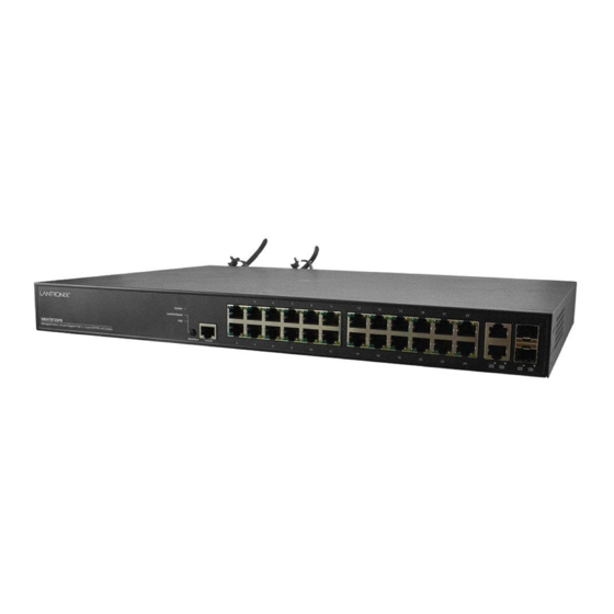
Introduction
The
SM24TBT2DPB
Managed Gigabit Ethernet PoE++ Switch with (24) 10/100/1000Base-T Ports + (2) 100/1000Base-X
SFP/RJ-45 Combo Ports. It comes with one PS-ACDC-1200 power supply and 19" rack mount brackets.
The
SM24TBT2DPB-2XPS
noted where they apply.
Note: See the full Install Guide for important information on Safety Warnings & Cautions, Ordering Information, Features,
Specifications, Front Panel and LED descriptions, Mode/Reset button, Back Panel, Related Manuals, Installation,
Package Contents, Mounting Safety Instructions, SFP Modules, Grounding, Power Supply, Cautions & Warnings, Saf-D
Connector, Connecting & disconnecting the AC Power Cord, DC Output Connector & Requirements, Temperature & AC
Input Requirements, Initial Switch Config, Cautions & Warnings, Electrical Safety Warnings, Troubleshooting, Regulatory
Agency, and Warranty information.
LED Descriptions
:
There are several types of front panel LEDs:
SYS (System) LED
indicates if the switch is powered up
correctly or if there is a system alarm triggered for
troubleshooting. Green On = switch is powered ON
correctly. Green Off = switch is not receiving power.
Red On = An abnormal state, such as exceeding
operating temperature range, was detected in the switch.
Mode LEDs
indicate the mode of all RJ45/SFP ports on the switch. You can press the Mode button sequentially to switch
between the two different modes (Link/Activity/Speed mode and PoE mode).
Link/Act/Speed
Green LED On = Port Status LEDs display link status, network activity and speed of each port.
RJ45 green = 1000 Mbps; amber = 10/100 Mbps. SFP green = 1000 Mbps; amber = 100 Mbps.
PoE LED
Green On = RJ45 Port Status LEDs display PoE powering status of each port.
Power Supply LEDs
on the back panel indicate Power Supply status. DC Green On = DC input is ready.
Red On = DC input has failed. Off = DC input is off. AC Green On = AC input is ready. Red On = AC input has failed.
Red Off = AC output is off.
Port Status
LEDs: indicate the current status of each RJ45 and SFP port. Press the Mode button for less than 2 seconds
to change the LED mode to Link/Act/Speed Mode or PoE Mode. See the Install Guide for LED behavior.
Mode/Reset Button
Change LED Mode
: press the button for 0~2 seconds; the SYS LED will be on green and the Port Status LED will
change based on the mode selected.
Reset the Switch
: press the button for 2~7 seconds; the SYS LED will blink green, and the Port Status LEDs will all be
off.
Restore to Defaults
: press the button for 7~12 seconds; the SYS LED will blink green, and all Port Status LEDs will stay
on.
Back Panel
: The back panel provides two power
supply slots and an airflow opening. Caution: Be sure
to leave adequate room for the airflow opening.
Installation
: Before beginning installation read the
Cautions and Warnings in the Install Guide.
33844 Rev. A
is the same except it comes with two PS-ACDC-1200 power supplies. Model differences are
https://www.lantronix.com
SM24TBT2DPB Quick Start Guide
Page 1 of 2
Advertisement
Table of Contents

Related Manuals for Lantronix SM24TBT2DPB


Summary of Contents for Lantronix SM24TBT2DPB
- Page 1 SM24TBT2DPB Quick Start Guide SM24TBT2DPB Managed PoE++ Switch, (24) 10/100/100Base-T ports + (2) 100/1000Base-X SFP/RJ45 Combo Ports Quick Start Guide Introduction SM24TBT2DPB Managed Gigabit Ethernet PoE++ Switch with (24) 10/100/1000Base-T Ports + (2) 100/1000Base-X SFP/RJ-45 Combo Ports. It comes with one PS-ACDC-1200 power supply and 19” rack mount brackets.
- Page 2 IEC adapter power cord, two 19” rack mount brackets, eight screws, one DB9F to RJ45 cable, four rubber feet, one LTX insert card, and one printed Quick Start Guide. If ordered as SM24TBT2DPB-2XPS, there will be two power supplies and two sets of Saf-D and power cables.
Need help?
Do you have a question about the SM24TBT2DPB and is the answer not in the manual?
Questions and answers