Table of Contents

Related Manuals for GEA HG Series


Summary of Contents for GEA HG Series
- Page 1 Bock Compressor HGX22P R410A Assembly instructions HGX22P/125-4 R410A HGX22P/125-4 S R410A HGX22P/160-4 S R410A HGX22P/190-4 R410A HGX22P/190-4 S R410A engineering for a better world GEA Refrigeration Technologies...
- Page 2 Observe the safety instructions contained in these instructions. These instructions must be passed onto the end customer along with the unit in which the compres- sor is installed. Manufacturer GEA Bock GmbH 72636 Frickenhausen Contact GEA Bock GmbH Benzstraße 7...
-
Page 3: Table Of Contents
Contents Page Safety 1.1 Identification of safety instructions 1.2 Qualifications required of personnel 1.3 General safety instructions 1.4 Intended use Product description 2.1 Short description 2.2 Name plate 2.3 Type key Areas of application 3.1 Refrigerants 3.2 Oil charge 3.3 Limits of application Compressor assembly 4.1 Setting up 4.2 Pipe connections 4.3 Pipes 4.4 Laying suction and pressure lines... -
Page 4: Safety
1| Safety 1.1 Identification of safety instructions: Indicates a dangerous situation which, if not DANGER! avoided, will cause immediate fatal or serious injury. Indicates a dangerous situation which, if not WARNING! avoided, may cause fatal or serious injury. Indicates a dangerous situation which, if not CAUTION! avoided, may cause fairly severe or minor injury. Indicates a situation which, if not ATTENTION! avoided, may cause property damage. INFO! Important information or tips on simplifying work. 1.2 Qualifications required of personnel WARNING! I nadequately qualified personnel poses the risk of accidents, the consequence being serious or fatal injury. Work on compressors must therefore only be performed by personnel with the qualifica- tions listed below: • F or example, a refrigeration technician, refrigeration mechatron-... -
Page 5: Intended Use
1| Safety 1.4 Intended use These assembly instructions describe the standard version of the HG22P R410A manufactured by Bock. The compressor is intended for use in refrigeration systems in compliance with the limits of application. Only the refrigerant specified in these instructions may be used. Any other use of the compressor is prohibited! WARNING! The compressor may not be used in potentially explosive environments! The Bock refrigerating compressor named in the title is intended for installing in a machine (within... -
Page 6: Product Description
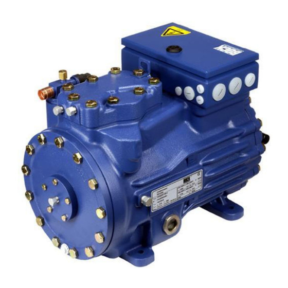
2 | Product description 2.1 Short description • Half-hemetic two-cylinder reciprocating compressor with oil pump lubrication. • Suction-gas-cooled drive motor • Compact dimensions, quiet running, high efficiency Transport eyelet Valve plate Name plate Oil pump Oil sight glass Fig. 1 Cylinder cover Terminal box Discharge shut-off valve Drive section Motor section... -
Page 7: Type Key
2 | Product description 2.2 Name plate (example) GEA Bock GmbH 72636 Frickenhausen, Germany HGX22P/125-4 S R410A AS33567A001 19,2/11,1 A 121 A 70 A 27/43 IP66 Öl: SE 55 Fig. 3 Voltage, circuit, frequency Type designation 50 Hz Nominal rotation speed Machine number... -
Page 8: Areas Of Application
3 | Areas of application 3.1 Refrigerants • R410A 3.2 Oil charge The compressors are filled at the factory with the following oil type: Fuchs Reniso SE 55 INFO! For refilling, we recommend the above oil types. Alternatives: see lubricants table, Chapter 7.5. 3.3 Limits of application ATTENTION! Compressor operation is possible within the operating limits shown in the diagrams. Please note the significance of the shaded areas. - Page 9 3| Areas of application R410A Fig. 4 Unlimited application range Supplementary cooling or reduced suction gas temperature Motor version S (more powerful motor) Evaporation temperature (°C) Condensing temperature (°C) Suction gas temperature (°C) Max. permissible operating pressure (LP/HP) : 27/43 bar LP = Low pressure HP = High pressure...
-
Page 10: Compressor Assembly
4| Compressor assembly INFO! New compressors are factory-filled with inert gas (3 bar nitrogen). Leave this service charge in the compressor for as long as possible and prevent the ingress of air. Check the compressor for transport damage before starting any work. 4.1 Setting up Use transport eyelet. Do not lift manually! Use lifting gear! Fig. -
Page 11: Pipes
4| Compressor assembly 4.3 Pipes Pipes and system components must be clean and dry inside and free of scale, swarf and layers of rust and phosphate. Only use air-tight parts. Lay pipes correctly. Suitable vibration compensators must be provided to prevent pipes being cracked and broken by severe vibrations. Ensure a proper oil return. Keep pressure losses to an absolute minimum. 4.4 Laying suction and pressure lines INFO! Proper layout of the suction and pressure lines directly after the... -
Page 12: Operating The Shut-Off Valves
4| Compressor assembly 4.5 Operating the shut-off valves Before opening or closing the shut-off valve, release the valve spindle seal by approx. ¼ of a turn counter-clockwise. After activating the shut-off valve, re-tighten the adjustable valve spindle seal clockwise. tighten release Valve spindle seal Fig. 11 Fig. 12 4.6 Operating mode of the lockable service connections Service connection closed Pipe connection Spindle Connection blocked Compressor Fig. 13 Opening the shut-off valve: Spindle: turn to the left (counter-clockwise) as far as it will go. —>... -
Page 13: Information For Contactor And Motor Contactor Selection
5| Electrical connection Electrical connection DANGER! H igh voltage! Risk of electric shock! Only carry out work when the electrical system is disconnected from the power supply! INFO! Connect the compressor motor in accordance with the circuit diagram (see inside of terminal box). Use suitable cable entry point of the correct protection type (see name plate) for routing cables into the terminal box. -
Page 14: Circuit Diagram Direct Start 230 V ∆ / 400 V Y Fe
5.3 Circuit diagram direct start 230 V ∆ / 400 V Y ... - Page 15 Alarm motor protection A2 Temperature rise R1, R2 Alarm high pressure X SS Terminal strip switch cabinet ...
-
Page 16: Electronic Trigger Unit Mp
5| Electrical connection 5.4 Electronic trigger unit MP 10 The compressor motor is fitted with cold conductor temperature sensors (PTC) connected to the electronic trigger unit MP 10 in the terminal box. Readiness to operate is signalled by the H3 LED (green) after the power supply is applied. In the case of excess temperature in the motor winding, the unit switches off the compressor and the H1 LED lights red. -
Page 17: Function Test Of The Trigger Unit Mp
5| Electrical connection 5.6 Function test of the trigger unit MP 10 Before start-up, troubleshooting or making changes to the control power circuit, check the functionality of the trigger unit: LED H1 LED H2 LED H3 Procedure green • Interrupt power supply (L1 or S1) • Release the motor temperature sensor connection (1 or 2) •... -
Page 18: Commissioning
6| Commissioning 6.1 Preparations for start-up INFO! In order to protect the compressor against inadmissible operating conditions, high-pressure and low-pressure pressostats controls are mandatory on the installation side. The compressor has undergone trials in the factory and all functions have been tested. There are therefore no special running-in instructions. -
Page 19: Refrigerant Charge
6| Commissioning 6.5 Refrigerant charge CAUTION! Wear personal protective clothing such as goggles and protective gloves! Make sure that the suction and pressure line shut-off valves are open. With the compressor switched off, add the liquid refrigerant directly to the condenser or receiver, breaking the vacuum. If the refrigerant needs topping up after starting the compressor, it can be topped up in vapour form on the suction side, or, taking suitable precautions, also in liquid form at the inlet to the evaporator. INFO! Avoid overfilling the system with refrigerant! I n order to prevent shifts in concentration, zeotropic refrigerant blends (e.g. -
Page 20: Connection Of Oil Level Regulator
6| Commissioning 6.8 Connection of oil level regulator The connection "O" is provided for installing an oil level regulator. A corresponding adapter must be obtained from the trade. 7| Maintenance 7.1 Preparation WARNING! Before starting any work on the compressor: Switch off the compressor and secure it to prevent a restart. Relieve compressor of system pressure. -
Page 21: Accessories
7| Maintenance 7.4 Accessories Available accessories can be found on the Internet at www.bock.de. 7.5 Extract from the lubricants table The oil type filled as standard in the factory is marked on the name plate. This oil type should be used as a preference. Alternatives are stated in the extract from our lubricants table below. Refrigerants Bock standard oil types Recommended alternatives... -
Page 22: Technical Data
8| Technical data 220-240 V ∆ / 380-420 V Y - 3 - 50 Hz 265-290 V ∆ / 440-480 V Y - 3 - 60 Hz... -
Page 23: Dimensions And Connections
9| Dimensions and connections Maße Zubeh Dimensions A Dimensions A Centre of gravity H,D1 H,D1 ca.550 ca.135 (328) ca.240 ca.20 ca.505 (470) Schwingungsdämpfer Vibration absorbers ca.135 Amortisseurs de vibration Massensch Centre of g Centre de g Anschlüsse Connections Raccords (328) ca.240 SV Saugabsperrventil, Rohr (L)*... -
Page 24: Declaration Of Conformity And Installation
EN 60034-1, EN 60204-1 DECLARATION OF INSTALLATION for using the compressors within the European Union (in accordance with Machinery Directive 2006/42/EC) The manufacturer: GEA Bock GmbH, Benzstraße 7 72636 Frickenhausen, Tel.: 07022/9454-0 hereby declares that the refrigerating compressor HGX22P - R410A complies with the basic requirements of Appendix II 1B of the Machinery Directive 2006/42/EC. The following harmonised standards have been applied:... -
Page 25: Service
The Bock service team can be contacted +49 7022 9454-0 by phone: via e-mail: bock@gea.com www.bock.de or on the Internet at: In addition, for German-speaking countries we have set up a toll-free Bock hotline 00 800 / 800 000 88 from Monday to Saturday between 8 am and 9 pm. - Page 26 Responsibility GEA-versity GEA Group is a global engineering company with multi-billion euro sales and operations in more than 50 countries. Founded in 1881, the company is one of the largest providers of innovative equipment and process technology. GEA Group is listed in the STOXX Europe 600 Index.
Need help?
Do you have a question about the HG Series and is the answer not in the manual?
Questions and answers