Table of Contents
Advertisement
Quick Links
Advertisement
Table of Contents

Related Manuals for GEA HG22e A


Summary of Contents for GEA HG22e A
- Page 1 GEA Compressor HG22e A Assembly instructions HG22e/125-4 A HG22e/125-4 S A HGX22e/125-4 A HGX22e/125-4 S A HG22e/160-4 A HG22e/160-4 S A HGX22e/160-4 A HGX22e/160-4 S A HG22e/190-4 A HG22e/190-4 S A HGX22e/190-4 A HGX22e/190-4 S A engineering for a better world...
- Page 2 Observe the safety instructions contained in these instructions. These instructions must be passed onto the end customer along with the unit in which the compres- sor is installed. Manufacturer GEA Bock GmbH 72636 Frickenhausen Contact GEA Bock GmbH Benzstraße 7...
-
Page 3: Table Of Contents
Contents Page Safety 1.1 Identification of safety instructions 1.2 Qualifications required of personnel 1.3 General safety instructions 1.4 Intended use Product description 2.1 Short description 2.2 Name plate 2.3 Type key Areas of application 3.1 Refrigerants 3.2 Oil charge 3.3 Limits of application Compressor assembly 4.1 Storage and transport 4.2 Setting up 4.3 Maximum permissible inclination 4.4 Pipe connections... -
Page 4: Safety
1| Safety 1.1 Identification of safety instructions: Indicates a dangerous situation which, if not DANGER! avoided, will cause immediate fatal or serious injury. Indicates a dangerous situation which, if not WARNING! avoided, may cause fatal or serious injury. Indicates a dangerous situation which, if not CAUTION! avoided, may cause fairly severe or minor injury. Indicates a situation which, if not ATTENTION! avoided, may cause property damage. INFO! Important information or tips on simplifying work. 1.2 Qualifications required of personnel WARNING! I nadequately qualified personnel poses the risk of accidents, the consequence being serious or fatal injury. Work on compressors must therefore only be performed by personnel with the qualifica- tions listed below: •... -
Page 5: Intended Use
Any other use of the compressor is prohibited! WARNING! The compressor may not be used in potentially explosive environments! The GEA refrigerating compressor named in the title is intended for installing in a machine (within the EU according to the EU Directives 2006/42/EC Machinery Directive, 97/23/EC Pressure Equipment Directive and 2006/95/EC – Low Voltage Directive). -
Page 6: Product Description
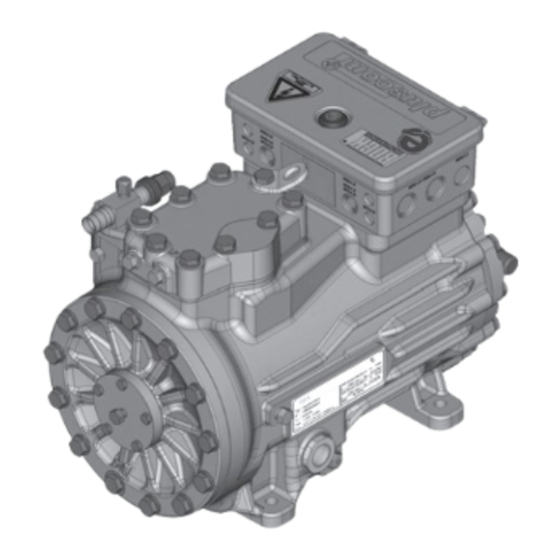
2| Product description 2.1 Short description • Semi-hermetic two-cylinder reciprocating compressor with oil pump lubrication. • Lightweight aluminum design • Suction gas cooled drive motor Transport eyelet Discharge shut- off valve Name plate Oil pump Oil sight glass Fig. 1 Cylinder cover Terminal box Valve plate... -
Page 7: Type Key
2| Product description Typschild (Beispiel) 2.2 Name plate (example) GEA Bock GmbH 72636 Frickenhausen, Germany HGX22e/190-4 S A AS35830A001 16,2/9,4A SE 55 Fig. 3 Typbezeichnung Spannung, Schaltung, Frequenz Type designation Voltage, circuit, frequency 50 Hz Maschinennummer Nenndrehzahl 50 Hz Machine number Nominal rotation speed... -
Page 8: Areas Of Application
- Use a thermal protection thermostat. - Do not operate an additional capacity controller. - Oil return at low frequency must be guaranteed. - Consultation with GEA. W hen operating in the vacuum range, there is a danger of air e ntering on the suction side. This can cause chemical reactions, a pressure rise in the condenser and an elevated compressed-gas... - Page 9 R134a Fig. 5 R407C Unlimited application range Fig. 6 Supplementary cooling or reduced suction gas temperature Supplementary cooling and reduced suction gas temperature Motor version S (more powerful motor) R404A/R507 Evaporating temperature (°C) Condensing temperature (°C) Suction gas superheat (K) Suction gas temperature (°C) Fig.
-
Page 10: Compressor Assembly
4 | Compressor assembly INFO! New compressors are factory-filled with inert gas (3 bar nitrogen). Leave this service charge in the compressor for as long as possible and prevent the ingress of air. Check the compressor for transport damage before starting any work. 4.1 Storage and transport Storage at (-30°C) - (+70°C), maximum permissible relative humidity 10% - 95%, no condensation Do not store in a corrosive, dusty, vaporous atmosphere or in a com- bustible environment. -
Page 11: Maximum Permissible Inclination
4 | Compressor assembly 4.3 Maximum permissible inclination ATTENTION! Poor lubrication can damage the compressor. Respect the stated values. max. 30°, max. 2 minutes max. 15°, continuous operation Fig. 14 4.4 Pipe connections The discharge and suction line valves have stepped internal diameters so that pipes with standard millimetre and inch dimensions can be used. -
Page 12: Pipes
4 | Compressor assembly 4.5 Pipes Pipes and system components must be clean and dry inside and free of scale, swarf and layers of rust and phosphate. Only use air-tight parts. Lay pipes correctly. Suitable vibration compensators must be provided to prevent pipes being cracked and broken by severe vibrations. -
Page 13: Operating The Shut-Off Valves
4 | Compressor assembly 4.7 Operating the shut-off valves Before opening or closing the shut-off valve, release the adjustable valve spindle seal by approx. ¼ of a turn counter-clockwise. After activating the shut-off valve, re-tighten the adjustable valve spindle seal clockwise. Release Valve spindle seal Tighten... -
Page 14: Electrical Connection 14 Gb
5| Electrical connection Electrical connection DANGER! H igh voltage! Risk of electric shock! Only carry out work when the electrical system is disconnected from the power supply! ATTENTION! When attaching accessories with an electrical cable, a minimum bending radius of 3 x the cable diameter must be maintained for laying the cable. INFO! Connect the compressor motor in accordance with the circuit diagram (see inside of terminal box). -
Page 15: Connection Of The Driving Motor F
5| Electrical connection 5.2 Connection of the driving motor The compressor is designed with a motor for star-delta circuits. Designation on the name plate Sticker on the terminal box ∆ / Y Star-delta start-up is only possible in the ∆ voltage range. Example: 230 V ∆... - Page 16 5.3 Circuit diagram for direct start 230 V ∆ / 400 V Y ...
-
Page 17: Electronic Trigger Unit Mp
Alarm Motor protection Overheating R1, R2 Alarm high pressure Terminal strip in the external switch cabinet ... - Page 18 5| Electrical connection 5.4 Electronic trigger unit MP 10 The compressor motor is fitted with cold conductor temperature sensors (PTC) connected to the electronic trigger unit MP 10 in the terminal box. Readiness to operate is signaled by the H3 LED (green) after the power supply is applied.
- Page 19 5 | Electrical connection 5.6 External connection of the MP 10 for terminal boxes at reduced height (Accessories) 0,5 mm² PTC1 PTC2 Terminal box Fig. 23 5.7 Function test of the trigger unit MP 10 Before start-up, troubleshooting or making changes to the control power circuit, check the functionality of the trigger unit: LED H1 LED H2 LED H3 Item...
-
Page 20: Commissioning
6| Commissioning 6.1 Preparations for start-up INFO! To protect the compressor against inadmissible operating conditions, high pressure and low pressure pressostats are mandatory on the installation side. The compressor has undergone trials in the factory and all functions have been tested. There are therefore no special running-in instructions. Check the compressor for transport damage! 6.2 Pressure strength test The compressor has been tested in the factory for pressure integrity. -
Page 21: Refrigerant Charge
6 | Commissioning 6.5 Refrigerant charge CAUTION! Wear personal protective clothing such as goggles and protective gloves! Make sure that the suction and discharge line valves are open. With the compressor switched off, add the liquid refrigerant directly to the condenser or receiver, breaking the vacuum. If the refrigerant needs topping up after starting the compressor, it can be topped up in vapour form on the suction side, or, taking suitable precautions, also in liquid form at the inlet to the evaporator. -
Page 22: Maintenance
Ref. No. Ref. No. Set gaskets 80590 Valve plate set 80305 80306 80306 Piston/connecting 80302 80303 80304 rod set Connecting rod set 08422 Only use original GEA spare parts! 7.4 Accessories Accessories available can be found on the Internet at www.gea.com... -
Page 23: Extract From The Lubricants Table
7.5 Extract from the lubricants table The oil type filled as standard in the factory is marked on the name plate. This oil type should be used as a preference. Alternatives are stated in the extract from our lubricants table below. Refrigerants GEA standard oil types Recommended alternatives Fuchs Reniso Triton SEZ 32 HFKW... -
Page 24: Technical Data
8| Technical data 220-240 V ∆ / 380-420 V Y - 3 - 50 Hz 265-290 V ∆ / 440-480 V Y - 3 - 60 Hz... -
Page 25: Dimensions And Connections
9 | Dimensions and connections Maße Zubehör / Dimensio Maße Zubehör / Dimension Maße Zubehör / Dim Centre of gravity ca.475 ca.475 ca.4 ca.285 DV B1 ¹ H,D1 H,D1 H,D1 ca.130 ca.130 ca.130 ca.240 ca.240 ca.240 46 (43) 4x 12 79 (74) Massenschwerpunkt Änderungen vorbehalte... -
Page 26: Declaration Of Installation
(in accordance with Machinery Directive 2006/42/EC) The manufacturer: GEA Bock GmbH, Benzstraße 7 D-72636 Frickenhausen, Tel.: 07022/9454-0 hereby declares that the refrigerating compressor HG22e A conforms to the essential requirements of Annex II 1B of the Machinery Directive 2006/42/EC. Applied harmonised standard: EN 12693:2008 and the corresponding standards referenced... -
Page 27: Service
11| Service Dear customer, GEA compressors are top-quality, reliable and service-friendly quality products. If you have any questions about installation, operation and accessories, please contact our technical service or specialist wholesaler and/or our representative. The GEA service team can be contacted by phone with a toll-free hotline 00 800 / 800 000 88 or via e-mail: refrigeration@gea.com Yours faithfully GEA Bock GmbH Benzstraße 7... - Page 28 • • GEA Group is a global engineering company with multi-billion euro sales and operations in more than 50 countries. Founded in 1881, the company is one of the largest providers of innovative equipment and process technology. GEA Group is listed in the STOXX Europe 600 index.
Need help?
Do you have a question about the HG22e A and is the answer not in the manual?
Questions and answers