Advertisement
Quick Links
Advertisement

Subscribe to Our Youtube Channel
Related Manuals for Matsusada EC Series


Summary of Contents for Matsusada EC Series
- Page 1 Instruction Manual EC series MODEL 024.9.005 Rev. 0.6 B/N 024.9.005 F-RA-001-3R0...
- Page 2 ◆ No patent liability is assumed with respect to the use of the information contained herein. Moreover, because Matsusada Precision is constantly striving to improve its high-quality products, the information contained in this manual is subject to change without notice.
- Page 3 Bistable push button switch for preventing electric shock) Indicates the possible danger of death if Bistable push button switch you drink it and burns or blindness if it attaches. Indicates the possible danger of exposure Alternative Current to radiation. Matsusada Precision...
- Page 4 Do not process or damage power cables It may result in electric shock or fire. Regarding the input voltage Check the page describing the input terminals and input voltage in the instruction manual. Do not provide any voltage out of the specifications. Matsusada Precision...
- Page 5 In order to avoid electric shock, ground the terminals to discharge using a short-circuit grounding apparatus and check the voltage again. The terminals here mean all terminals like input and output terminals and terminals for communications and remote controls. Matsusada Precision...
- Page 6 It requires to be replaced at regular intervals to extend the lifetime. For the replacement, contact us. (It requires a replacement charge separately. Do not replace it by yourself, as there is a risk of electric shock.) Matsusada Precision...
- Page 7 1 Introduction 1 Introduction 1-1 Introduction Thank you very much for your purchase of our product HIGH VOLTAGE POWER SUPPLY. We have done our best for the quality control of the unit. Please handle this unit properly according to this instruction manual so that you can use the full performance of this unit safely for long.
- Page 8 1 Introduction 1-4 Caution for handling WHEN TOUCHING LOAD AFTER TURNING OFF A HIGH VOLTAGE 1. Make the setting of an output voltage to zero (0). Turn off the HV ON/OFF switch. 2. Make sure that the output voltage is zero with the output voltmeter of this unit. 3.
-
Page 9: 1-5 Troubleshooting
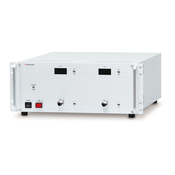
1 Introduction FOR SAFER OPERATION 1. It would be rather safe if the power supply is operated on an insulation board, which is withstand the voltage used. 2. Try to handle the power supply or load with your right hand, and try to keep the left hand, for example, putting it pocket. - Page 10 2 Exterior view diagram 2 Exterior view diagram Front panel ⑦ ⑧ ⑤ ⑥ ⑨ REMOTE LOCAL + + Adj. Adj. POWER - - ① ③ ② ⑩ ④ ⑪ ① POWER ON/OFF switch ⑦ Local / Remote change switch ②...
- Page 11 3.Operation Manual 3.Operation manual 3-1 Outline This unit is a polarity switchable bi-polar high voltage power supply with 2 outputs channels for electrostatic chuck application. 3-2 Operation method 1. Upon confirming the connection made with this unit as specified (Refer to 1-4[HOW TO GROUND]), operate it.
- Page 12 3.Operation Manual Control connector ・・・ D-sub 25S type PIN 7 CH① Output Relay PIN 6 CH① Forced grounding CH① Polarity change PIN 8 PIN 5 CH① Monitor Common Common PIN 9 PIN 4 CH① Output current monitor output CH① HV ON/OFF PIN10 PIN 3 CH①...
- Page 13 3.Operation Manual d. Interlock High voltage output can be cut off with external switch off. For safety reason, once the output is cut off, the unit shall not resume the output even turning the external switch back on. To reset this status, turn the Power switch on after shorting the interlock terminal. Interlock action Interlock action by switch SHORT...
- Page 14 3.Operation Manual g. Output voltage monitor ±10V output for the maximum rated output voltage. Output impedance is 1k ohm. The polarity of monitor output is identical to that of high voltage output. ⑤ ③ ⑱ ⑯ CH① CH② Vmoni Vmoni h.
- Page 15 3.Operation Manual k. Forced discharge High voltage output can be compulsory grounded with the function of forced grounding terminal. HV output HV CH① CH② ⑨ ⑥ ⑲ Forced ground action Forced ground action by SHORT …… Output Ground switch switch switch O P E N ……...
- Page 16 3.Operation Manual Precautions in using the open collector *1 Use the open collector according to the following rule. Rule of open collector Output Switch Open collector Short Under 0.4V (10mA) Open Over 2V (Open 5V)
-
Page 17: Option Function
4 Explanation of optional function 4 Explanation of optional function 4 Option function This product is equipped with features of checked in the table below. Name of option □ Output relay (-LRy) □ RF filter 13.56MHz (-LRf(13.56M)) □ RF filter 500kHz (-LRf(500k)) □... - Page 18 4 Explanation of optional function 4-2 RF Filter 13.56MHz (LRf (13.56M)) RF filter for 13.56MHz is incorporated at output terminal. 4-3 RF Filter 500kHz (LRf (500k)) RF filter for 500MHz is incorporated at output terminal. 4-4 INPUT AC230V (L(230V)) In a standard, input voltage is AC115V±10%. This option is provided input AC230V±10% NOTE: AC input cord for 100VAC input type and 200VAC input type is different.
Need help?
Do you have a question about the EC Series and is the answer not in the manual?
Questions and answers