IEI Technology IMBA-C2360-i2 Quick Installation Manual
Atx motherboard
Hide thumbs
Also See for IMBA-C2360-i2:
- Quick installation manual (21 pages) ,
- User manual (182 pages)
Advertisement
Quick Links
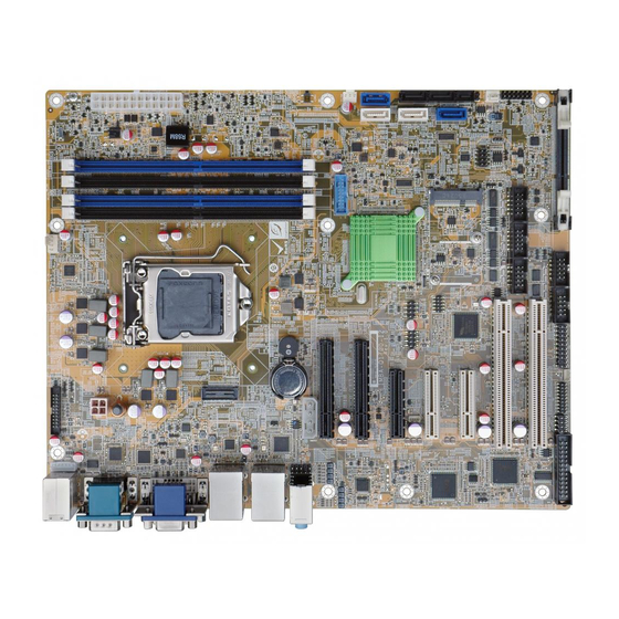
ATX Motherboard supports 14nm LGA1151 Intel® Xeon® E3 v5 series,
Core™ i3,Pentium® /Celeron® processor per Intel® C236 , DDR4,
Three Independent Displays VGA/ DVI-D / HDMI 2.0/, Dual Intel® PCIe
GbE, USB 3.0, SATA 6Gb/s, HD Audio, IPMI2.0 and RoHS
Quick Installation Guide
Package List
IMBA-C2360-i2 package includes the following items:
1 x IMBA-C2360-i2-R10 Single board computer
1 x I/O shielding
2 x SATA cable
1 x One Key Recovery CD
1 x QIG
1 x Utility CD
©2016 Copyright by IEI Integration corp.
All manuals and user guides at all-guides.com
IMBA-C2360-i2
Version 1.0
Apr 07, 2016.
All rights reserved.
1
Advertisement

Related Manuals for IEI Technology IMBA-C2360-i2


Summary of Contents for IEI Technology IMBA-C2360-i2
- Page 1 IMBA-C2360-i2 Quick Installation Guide Version 1.0 Apr 07, 2016. Package List IMBA-C2360-i2 package includes the following items: 1 x IMBA-C2360-i2-R10 Single board computer 1 x I/O shielding 2 x SATA cable 1 x One Key Recovery CD 1 x QIG 1 x Utility CD ©2016 Copyright by IEI Integration corp.
-
Page 2: Specifications
All manuals and user guides at all-guides.com Specifications CPU: LGA1151 Intel® Xeon® E3 v5 series, Core™ i3, Pentium® /Celeron® processor supported System Chipset: Intel® C236 Memory: Four 288-pin 2133 MHz dual-channel DDR4 SDRAM unbuffered DIMMs support up to 64 GB BIOS: UEFI BIOS Graphic Engine: Intel®... - Page 3 All manuals and user guides at all-guides.com 1 x USB 3.0 (2x10 pin, P=2.0) 1 x USB 2.0 (Type A) 4 x USB 2.0 (2x4 pin, P=2.0) 4 x RS-232 (2x5 pin, P=2.54) SMBus: 1 x SMBus (1x4 pin) I²C: 1 x I²C (1x4 pin) TPM: 1 x TPM connector (2x10 pin) Audio: Realtek ALC662 HD codec supports 5.1-channel...
-
Page 4: Ordering Information
Operation Humidity: 10% ~ 95%, non-condensing Dimensions: 244mm x 305mm Weight: GW:1200g, NW: 700g Ordering Information IMBA-C2360-i2-R10: ATX Motherboard supports 14nm LGA1151 Intel® Xeon® E3 v5 series, Core™ i3,Pentium® /Celeron® processor per Intel® C236 , DDR4, Three Independent Displays VGA/ DVI-D / HDMI 2.0/, Dual Intel®... - Page 5 All manuals and user guides at all-guides.com CF-1156C-RS: LGA1155/1156 kit, 1U chassis compatible, 45W CF-1156D-RS: LGA1155/1156 kit, 1U chassis compatible, 65W CF-1156E-R11: High-performance LGA1155/1156 cooler kit, 95W DP-DP-R10: DisplayPort to DisplayPort converter board (For iEi IDP connector) DP-DVI-R10: DisplayPort to DVI-D converter board (For iEi IDP connector) DP-HDMI-R10: DisplayPort to HDMI converter board (For iEi IDP connector) DP-LVDS-R10:...
-
Page 6: Jumpers Setting And Connectors
All manuals and user guides at all-guides.com Jumpers setting and connectors LABEL FUNCTION J_CMOS1 Clear CMOS button SW_BIOS1_2 Switch BIOS1 or BIOS2 (option function) Flexibility for PCIE_2 Slot & PCIE_3 slot Flexibility I/O (option function) J_ATX_AT1 AT/ATX Power Mode Setting USB SW1 Power USB Power Setting USB SW2 Power... - Page 7 All manuals and user guides at all-guides.com CPU12V1 +12V Power Source Connector ATXPWR1 PCI ® E Power Connector TPM1 TPM Connector EC Debug Port Connector JSPI1 Flash SPI ROM JSPI2 Flash EC ROM SMB1 SMBUS Connector I2C1 I2C Connector (to EC) LED_LAN1 LAN1 LINK LED Connector LED_LAN2...
- Page 8 All manuals and user guides at all-guides.com Flexibility I/O: Flexibility for PCIE_2 Slot & PCIE_3 slot (option func tion) BIOS1(a) & BIOS1(b) Aptio Setup Utility – Copyright (C) 2015 American Megatrends, Inc. Chipset PCI Express Configuration (BIOS No.1) PCIE_2 Slot Mode PCIe_1x4_slot PCIE_3 Slot Mode [(a) PCIE_3 Slot:...
-
Page 9: Pin Description
All manuals and user guides at all-guides.com USB SW1 Power, USB SW2 Power: USB power setting USB SW1 DESCRIPTION +5V DUAL 5V DUAL (Default) Aptio Setup Utility – Copyright (C) 2012 American Megatrends, Inc. Chipset Auto Power Button Status [Disabled(ATX)] Restore AC Power Loss [Last State] ------------------... - Page 10 All manuals and user guides at all-guides.com VIDEO1 : 15-pin Female Connector PIN NO. DESCRIPTION PIN NO. DESCRIPTION GREEN BLUE Hot plug detect DDCDA HSYNC VSYNC DDCCLK VIDEO1: DVI-I(Dual Link)+CRT PIN NO. DESCRIPTION PIN NO. DESCRIPTION DVI_DATA1 GREEN BLUE DVI_DATA2# HPDET DVI_DATA2 DVI_DATA0#...
- Page 11 All manuals and user guides at all-guides.com HDMI1: HDMI Connector (support HDMI2.0) PIN NO. DESCRIPTION PIN NO. DESCRIPTION HDMI_DATA2 HDMI_DATA2# HDMI_SCL HDMI_DATA1 HDMI_SDA HDMI_DATA1# HDMI_DATA0 HDMI_HPD HDMI_GND HDMI_DATA0# HDMI_GND HDMI_CLK HDMI_GND HDMI_GND HDMI_CLK# DP1: Display port connector (support 2K resolution) PIN NO.
- Page 12 All manuals and user guides at all-guides.com LAN1_USB1: Ethernet and USB 3.0 connectors USB1: External USB 3.0 connectors PIN NO. DESCRIPTION PIN NO. DESCRIPTION USB_DATA- USB_DATA- USB_DATA+ USB_ DATA+ USB3_RX- USB3_RX- USB3_RX+ USB3_ RX+ USB3_TX- USB3_TX- USB3_TX+ USB3_TX+ LAN1: RJ-45 LAN connector PIN NO.
- Page 13 All manuals and user guides at all-guides.com LAN2_USB2: Ethernet and USB 3.0 connectors USB2: External USB 3.0 connectors PIN NO. DESCRIPTION PIN NO. DESCRIPTION USB_DATA- USB_DATA- USB_DATA+ USB_ DATA+ USB3_RX- USB3_RX- USB3_RX+ USB3_ RX+ USB3_TX- USB3_TX- USB3_TX+ USB3_TX+ LAN2: RJ-45 LAN connector PIN NO.
- Page 14 All manuals and user guides at all-guides.com KB_MS1: 6-pin header Keyboard/Mouse Connector PIN NO. DESCRIPTION PIN NO. DESCRIPTION Mouse Data Mouse Clock Keyboard Data Keyboard Clock USB1, USB2: Internal USB 2.0 connectors PIN NO. DESCRIPTION PIN NO. DESCRIPTION USB_DATA- USB_DATA+ USB_DATA+ USB_DATA- USB3 ®...
- Page 15 All manuals and user guides at all-guides.com COM5,COM6:Internal RS-232/RS-422/RS-485 serial port connectors PIN NO. DESCRIPTION PIN NO. DESCRIPTION AUDIO_CV1 : Audio Line-In/Out MIC Connector PIN NO. DESCRIPTION Line_In CD/DVD or other audio source input port (Blue) Line_Out Connect this port to headphone or speaker (Green) Microphone Connect this port to microphone...
- Page 16 All manuals and user guides at all-guides.com SATA1, SATA2, SATA5: Serial ATA 3.0 connectors PIN NO. DESCRIPTION PIN NO. DESCRIPTION SATA_RX ® SATA_TX+ SATA RX+ SATA_TX ® SATA3, SATA4: Serial ATA 3.0 Connector or PCIEX4_3 Slot PIN NO. DESCRIPTION PIN NO. DESCRIPTION SATA_RX ®...
- Page 17 All manuals and user guides at all-guides.com CN2: M-SATA card connector PIN NO. DESCRIPTION PIN NO. DESCRIPTION PCIE_WAKE# +3.3V 1.5V MSATA_CLK# MSATA _CLK PLTRST_N +3.3V PLTRST_N SATA_RX+ +3.3V SATA_RX- 1.5V SMB_CLK SATA_TX- SMB_DATA SATA_TX+ USB_DATA- USB_DATA+ +3.3V +3.3V +3.3V CLINK_CLK CLINK_DATA 1.5V CLINK_RST#...
- Page 18 All manuals and user guides at all-guides.com SYS_FAN1, SYS_FAN2: System fan connector PIN NO. DESCRIPTION PIN NO. DESCRIPTION FANIO +12V (PWM) DIO1 : Digital Input / Output Connector PIN NO. DESCRIPTION PIN NO. DESCRIPTION Output 3 Output 2 Output 1 Output 0 Input 3 Input 2...
- Page 19 All manuals and user guides at all-guides.com ATXPWR1: PCI ® ® ® ® E Power Connector PIN NO. DESCRIPTION PIN NO. DESCRIPTION +12V TPM1: Trusted Platform Module Connector PIN NO. DESCRIPTION PIN NO. DESCRIPTION LCLK LFRAME# LRERST# LAD3 LAD2 +3.3V LAD1 LAD0 SB3V...
- Page 20 All manuals and user guides at all-guides.com JSPI1: Flash SPI ROM connector PIN NO. DESCRIPTION PIN NO. DESCRIPTION +3.3V SPI_CS# SPI_SO SPI_CLK SPI_SI JSPI2: Flash EC ROM connector PIN NO. DESCRIPTION PIN NO. DESCRIPTION +3.3V SPI_CS# SPI_SO SPI_CLK SPI_SI SMB1: SMBUS connector PIN NO.
- Page 21 All manuals and user guides at all-guides.com Board Layout: Jumper and Connector Locations (Unit: mm)
Need help?
Do you have a question about the IMBA-C2360-i2 and is the answer not in the manual?
Questions and answers