Table of Contents
Advertisement
Quick Links
Advertisement
Table of Contents

Related Manuals for Hoggi SUPRA 2.0


Summary of Contents for Hoggi SUPRA 2.0
- Page 1 Partnerschaft für mobile Kinder SUPRA 2.0 Service instructions...
-
Page 2: Table Of Contents
SUPRA 2.0 - Service and maintenance instructions Content Page Model identification & basic configuration 1.1 Model identification (label)_____________________________________________________ 4 1.2 Basic configuration___________________________________________________________ 5 1.3 Environmental conditions _____________________________________________________ 5 Overview SUPRA 2.0 _____________________________________________________________ 6 Common information ____________________________________________________________ 7 3.1 Preface ___________________________________________________________________ 7 3.2 Application _ ________________________________________________________________ 8 3.3 Declaration of conformity______________________________________________________ 8 3.4 Terms of warranty ___________________________________________________________ 8... - Page 3 7.10 Push bar and handles, One hand push-handle _ ___________________________________ 30 7.12 Tie down kit _______________________________________________________________ 31 7.13 Back extension ____________________________________________________________ 31 7.14 Footrest bracket _________________________________________________________31-32 7.15 Clothes guard & fender ____________________________________________________32-33 7.16 Therapy tray ______________________________________________________________ 33 7.17 Spoke guards _____________________________________________________________ 33 7.18 Calf strap _________________________________________________________________ 33 7.19 Anti tip and tip assist ________________________________________________________ 34 7.15 Abduction block ____________________________________________________________ 34 7.16 Seat and back cushion ______________________________________________________ 34 7.17 Headrest _________________________________________________________________ 35 7.18 Back cover & edge protection _________________________________________________ 35 7.19 Belt fixations ______________________________________________________________ 36...
-
Page 4: Model Identification (Label)
1 Model identification 1.1 Model identification (label) (The label is attached to the axle tube) Colour code 3281-00SB-XXX Article number SUPRA 2.0 Hoggi GmbH Size Gr. X Eulerstr. 27 56235 Ransbach-Baumbach MADE IN GERMANY Serial number max. load XXkg CE label (01)04047349096062(21)202178999 3281-00SB-XXX Classification / Product name SUPRA 2.0 Hoggi GmbH Gr. X Eulerstr. 27 56235 Ransbach-Baumbach Date of manufacture MADE IN GERMANY max. -
Page 5: Basic Configuration
1.2 Basic configuration - Rigid frame active wheelchair in aluminium construction, powder-coated; seat depth grows with the user - 3 frame sizes: Frame size 1: SW 24-34cm in 2cm-Steps, SD 23-35 cm Frame size 2: SW 28-38cm in 2cm-Steps, SD 24-44 cm Frame size 3: SW 28-38cm in 2cm-Steps, SD 29-49 cm - HOGGI light rear wheels inclusive push rims (removable via quick-release axle) - Clothe cover side panels straight - Camber 6°, 9° or 12° - Backrest angle: 70° up to 105° adjustable - adjustable back cover - Front seat heights: 38 cm up to 51 cm - Seat angle: 0° bis ca. 10° - Convertible to other seat widths - Footrest: Standard - Load capacity: 60 kg (SW 24-32), 80 kg (SW 34-38), 100 kg (SW 40-44) 1.3 Environmental conditions Environmental factors such as temperature and humidity can damage the wheelchair. The manufacturer recommends not condensing the SUPRA 2.0 at ambient temperatures bet- ween -20 ° C and + 40 ° C and a humidity of 5 to 100%. Caution: Prolonged exposure to the sun may cause parts of the wheelchair to become hot. Be sure to! -
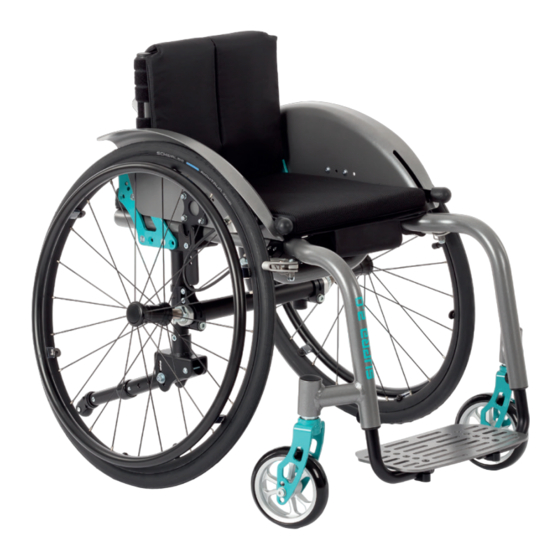
Page 6: Overview Supra 2.0
2 SUPRA 2.0 Overview Pos Article number Article description Front wheels 1281-002x Wheel fork 3210 11SB Axle tube and adapter housing Tires 3281-12SB Rear axle mounting Back base 3201-340x Mounting parts for back base 3218 xxxx Frame SUPRA 2.0 32xx-4xxx Footrest hanger... -
Page 7: Common Information
3 Common Information 3.1 Preface Thank you for selecting the SUPRA 2.0 wheechair. We have designed this high-quality pro- duct to make your life safer and easier, and we’ve included this manual to help you use and care for it. Please read the following instructions to make sure you use this product as re- commended. If you have any further questions, or if you have any problems, please contact your healthcare provider. We hope that SUPRA 2.0 meets your expectations. We reserve technical modifi cations regarding the specifi ed model in this manual. Before using the wheechair the fi rst time, this manual has to be read and understood by patient and support personnel in oder to ensure a safe handling with the wheelchair. Regular maintenance is important - it increases safety and prolongs the life of the product. Every rehab product should be checked and serviced once a year. However, it is recommended to check, readjust and, if necessary, service products with a high frequency of use, with users in growth or users with a changing clinical picture at 6-month intervals. Only original spare parts should be used for all service and maintenance work. The service and maintenance work described here should only be carried out by trained specialist personnel and not by the user of the aid. These service and maintenance instructions refer to the respective spare parts catalogs and operating instructions of the products described. Please use all documents together. Use the maintenance schedule (Chapter 5.2, Checklist to tick off) as a copy template. Retain completed maintenance schedules and provide a copy to the customer. User manual SUPRA 2.0 1910-0049-EN... -
Page 8: Application
3.2 Application SUPRA 2.0 wheelchair is designed solely for individual indoor and outdoor use by childern and adolescents who are unable to walk or who have a walking impediment, and can be operated by the patient or by another person. Assistance may be required due to: - Paralysis (paraplegia / tetraplegia or tetraparesis) - Loss of limbs (dysmelia/lower limb amputation) - Infantile/spastic cerebral palsy - Spina Bifida - Muscle and nerve disorders - Osteogenesis Imperfecta - Poliomyeliti SUPRA 2.0 wheelchair is able to be used for further service. For further service the product has to be cleaned and sanitised efficiently. Afterwards the product has to be checked concerning condition, wearout and damage by an authorised technician. All damaged and inapropptiate parts need to be changed. Some components can be used again, e.g. Rear wheels, steering wheels or push handles. Please see also the service manual for detailled information. 3.3 Declaration of Conformity HOGGI GmbH as manufacturer declares under sole responsibility that the SUPRA 2.0 active wheelchair meets the general safety and performance requirements to Annex I of the Regulation (EU) 2017/745 of the European Parliament and of the Council. Applicable harmonized standards have been applied. SUPRA 2.0 meets the requirements of ISO 7176-8, DIN EN ISO 12182 and DIN EN ISO 12183. 3.4 Terms of Warranty Warranty applies only when the product is used according to the specified conditions and for the intended purposes, following all manufacturer’s recommendations.The manufacturer is not responsible for damages caused by components and spare parts not approved by the manufacturer. See also § 8 of terms and conditions on:... -
Page 9: Service And Repairs
3.6 Service and repairs Service and repairs on the SUPRA 2.0 wheelchair may only be carried out by your speci- alist dealer. In case of problems, contact your responsible specialist dealer. In case of re- pairs, you will only receive original spare parts there. Spare parts and replacement units are available during the entire service life of the pro- duct, but only for a maximum of 2 years after the sale of the last product in this series. The wheelchair is custom made for the first time user. Therefore, no replacement wheel- chair is available in the initial configuration. In order to ensure a correct spare parts delive- ry the serial no. of your wheelchair is required. We are happy to help you find a dealer near you. You can reach us at: info@hoggi.de 3.7 Packing and shipping instructions If SUPRA 2.0 has to be sent back to the manufacturer for repair or exchange the product must be thoroughly cleaned/disinfected beforehand and put in a hygienically safe conditi- Packaging is done by wrapping the product in a clean film, ideally with air cushions and the subsequent use of a sufficiently large cardboard box, so that no transport damage can occur. -
Page 10: Safety Instructions
4 Safety instructions 4.1 Meaning of symbols Caution! Warning of possible danger of accident and injury. Warning of possible technical damage. Information! About use of product. Information! For service-personnel. Attention! Read manual before use! Common safety instructions For all maintenance and repair work, you should generally observe a few points: Attention! Familiarize yourself with the functions of the product. If you are not familiar with the product, study the user manual before testing. If no user manuals are available, request them from us. You can also download documents from our homepage at: www.hoggi.de Attention! Study the service and maintenance instructions before starting work. Attention! Use suitable tools (see page 4 ff.). Attention! Wear suitable clothing and, if necessary, gloves and protective goggles. Attention! Secure the product from tipping over or falling down, e.g. from the workbench. Attention! Clean / disinfect the product before starting the test. If necessary, observe the instructions in the user manual and product-specific test instructions. Note! Screws and nuts with thread locking are used for a large number of screw connections. If you have to open such screw connections, replace the respective nut or screw with one with new thread locking. If new nuts or bolts with thread locking are not available, use liquid thread locking compound with medium strength (e.g. Loctite 241 or Euro Lock A24.20). -
Page 11: Required Tools And Maintenance Schedule
5 Required tools and maintenance schedule 5.1 Required tools The following list shows the tools and utilities required for service. Reversible ratchet and sockets Torque wrench Wrench Measuring ranges 5-50 Nm size 8-24 Size 6 - 24 Hexagon wrench Screwdriver Phillips screwdriver Gr. 3 - 6 Blade width 2.5 3.5 and 5.5 Size 2 Plastic hammer Hammer approx. 300 g Carpet knife with sickle and standard blade Side cutter Liquid thread locking Riveting pliers for rivets up to „medium strength 5 mm... -
Page 12: Maintenance Schedule
Customer: Maintenance schedule SUPRA 2.0 for regular inspection Active wheelchair .......... Area Check (Checklist to tick off Pos. Serial number: Function / Setting Screw connections none (see instruction manual) damage / defor- ........mation 1. Basic product Frame and seat unit - Damages Back section and latching unit - Backrest angle - Backrest height Bearing plate and axle mount - Seat depth - Active degree Axle tube - Seat height - Seat angle - Camber Braking system - Brakes Wheel fork holder - Swivelling the wheel forks Front wheels - Tires... - Page 13 Function / Setting Screw connections none (see instruction manual) damage / defor- mation 2. Accessories Push bar / push handles - Höhenverstellung One hand push handle - Winkelverstellung Griffhalter - Abnehmen Tie down kit - Bracket Back rest extension - Height adjsutment - Cushion Footrest hanger & footrest - Lower leg length - Folding away the footrest - Angle adjustment Clothe cover & wheel covers - Removal - Height adjustment - Cushion Therapy tray - Clamping unit Spoke guard - Spoke guard Calf strap - Tension and hold Anti tip and tip assist - Anti tip - Swivel away - Angle adjustment Abduction block - Bracket...
-
Page 14: Seat Settings
6. Seat settings 6.1 Seat height & seat angle The seat height and angle of the SUPRA 2.0 can be adjusted via different steering wheel and caster fork sizes and by moving the drive wheel axle in relation to the rear wheel axle mount. Seat height: 38 - 51 cm Seat angle: 0° - 10° To move the rear wheel axle, the corresponding screws must be loosened. The axle can then be moved along the axle mountings. When the desired position is reached, tighten the bolts again. 6.2 Seat depth The seat depth of SUPRA 2.0 is realised by shifting the rear axle frame in relation to the seat frame. Size 1: 23 - 35 cm Size 2: 24 - 44 cm Size 3: 29 - 49 cm... -
Page 15: Active Degree
After loosening the screw connection of the rear axle frame and the clamping strut in the frame tube, the entire rear axle mount can be moved. 6.3 Active degree The active degree describes the ratio of the position of the backrest relative to the drive wheel axis. The further the backrest is set behind the the drive wheel axle, the more active SUPRA 2.0 can be driven. Conversely, a setting above, or in front of, the drive axle means a more stable driving position. Caution. Settings with a high degree of activity require an experienced driver and the use of an anti-tippers! SUPRA 2.0 offers an adjustment range of 0 - 10 cm. For adjustment, the corresponding screw connections of the backrest base to the rear axle mount must be loosened, moved in the slotted holes or moved. Active degree setting 0 - 3 cm 0 - 3 cm 2 - 5 cm and 2 - 5 cm. Alignment of the rear axle frame to the front... - Page 16 Active degree setting 5 - 8 cm 5 - 8 cm 7 - 10 cm and 7- 10 cm. Alignment of the rear axle frame to the rear Depending on the seat depth and degree of activity, the 3 frame sizes are as follows:...
- Page 17 Conversion rear axle frame If a change from <= 5cm to >= 5cm is made when setting the active de- gree to >= 5cm, the rear axle mount must be converted and aligned with the long end to the front. The first step is to remove the two screws to the bearing plate on both sides, so that the complete back base can be removed. The screw connections from the rear axle mount to the upper frame must now be loosened and removed on both sides. Loosen the screw connections from the axle mount to the rear axle frame. A rear axle frame can now be pulled out of the clamp Replace the axle frame in the new orientation and rotate the axle by 180°.
- Page 18 Loosen the screw connection to the axle mount and remove the screws completely. Then remove the camber adapters and pull the axle out of the holder. On the opposite side, also align the rear axle frame in the new position and screw it in place. Put the clamp back on the rear axle frame with the alignment to the front. Insert the axle and screw the camber adapters tight again. The exact alignment towards the ground must be checked with a spirit level. Important, regardless of whether the alignment is to the front or rear, the rear axle frame must always be mounted as shown with the narrow side facing outwards! Inside Outside...
- Page 19 Depending on how the seat depth or the degree of activity has been ch- anged, readjustment of the brakes and/or the wheel covers is necessary. The side parts can be screwed in 4 positions with the locking sword. This means that the cover can always be aligned centrally over the wheel. Position 1 and 2 Position 3 and 4...
-
Page 20: Back Height
6.4 Back height SUPRA 2.0 is equipped either with an adaptable backrest covering or with a back plate. The basic backrest heights are 20/25/30/35 cm. Adjustable backrest covering Back panel The fastening is done via clamps to the back frame. By loosening the screw connections, the height of the back plate can be adjusted. A different backrest height can also be achieved by moving the screws into other slotted holes. To obtain a corresponding adjustment range, telescopic tubes for back height adjustment or single push handles must be additionally equipped. These offer 10 cm length (back height 20 cm only 5 cm possible for constructional reasons.) - 20 up to 25 cm This results in the following adjustment range: - 25 up to 35 cm - 30 up to 40 cm - 35 up to 45 cm Telescopic tubes Single push handles Height adjustment by loosening the screw on the back frame. -
Page 21: Back Angle Adjustment
6.5 Backrest angle adjustment Back rigid The rigid back offers an adjustment range of 70° to 115°. By placing the screw from the outside in one of the front two holes in the bearing plate, the desired range can be preset. Each hole offers an adjustment range of approx. 22.5°. Middle hole: approx. 70°- 92,5° Front hole: approx. 92,5°- 115° Via the 5 hole positions of the back base and the spacer, fine adjustment can be made within the 22.5° adjustment range, depending on how the screw is inserted. The further forward the screw connection, the smaller the back angle. The backrest frame is always measured in relation to the seat frame. The 90° backrest angle results from the centre-to-centre position. Back with relief position and foldable The back angle can be varied between two positions, the driving position and the the driving position and the relief position (15° difference). In addition, the back can be folded down and fixed for transport. for transport. It is released by means of a locking bolt on the back. Back folded down and fixed. Unlike the rigid back, the screw connection is made from the inside. The adjustment range is also 70° to 115°, depending on the hole position in which the screw is inserted. In addition, a further 15° is achieved with the relief position, i.e. a total of 70° to 130°. -
Page 22: Lower Leg Length
6.6 Lower leg length The lower leg length can be adjusted between 16 and 46 cm depending on the frame size and footrest variant. The adjustment is made by loosening the screw connection on the frame tube. With the variant for short lower leg lengths it may be necessary to shorten the tubes, as otherwise contact with the contact with the floor! This results in the following possible combinations: 6.7 Footrest angle and depth Depending on the footrest version, the angle can be adjusted by loosening the front screw. The depth can be adjusted by repositioning the footrest and using the other holes. -
Page 23: Armrest Height
6.8 Armrest height SUPRA 2.0 can either be equipped with clothe cover and PU armrests, or equipped with a wheel cover with armrests. These are always height-adjustable and removable. Clothe cover with PU armrests. The height is adjusted by moving the armrest in relation to the clothe cover. This results in an adjustment range of approx. 3 cm. The elongated holes can also be used to adjust the angle to compensate for a steep seat angle. Another adjustment option is the positioning of the insertable sword. Depending on the screw position, the adjustment range is of 7 cm. In total, the height can be adjusted by 10 cm. In combination with the wheel cover, there is also an adjustment range of 10 cm. The wheel cover is released by pressing the push button on the inside. push button. -
Page 24: Wheel Fork Adjustment
6.9 Wheel fork adjustment Depending on whether the seat adjustment has been changed, the the alignment of the wheel fork must be adjusted accordingly. To do this, first completely loosen both the upper nut and the side grub screw. Then slightly tighten the upper screw connection again and align the axle with the help of a spirit level by slightly turning the grub screw clockwise with an Allen key. If the axle is now aligned straight, the upper screw connection can be tightened firmly with 20 Nm. Finally, check again with the spirit level and tighten the grub screw again. -
Page 25: Maintenance Schedule
7. Maintenance schedule 7.1 Frame & seat unit Functional test: - Check for general damage to frame, seat cover or seat panel - Screw connections of the seat cover or the seat panel 7.2 Back section and latching unit Functional test: - Check for general damage (Velcro, sheet metal, telescoping, covers) - latching pin pull intact with folding backrest - Correct back angle Check the screw connections: - Screwing of the latching unit - Screwing of the back base - Telescoping - Clamps on back plate 7.3 Bearing plate and axle mount Functional test: - Check for general damage - correct active degree - correct seat depth Check of the screw connections: - Seat depth adjustment under the axle frame - Active degree adjustment, screw connection axle frame and bearing plate... -
Page 26: Axle Tube
7.4 Axle tube Functional test: - Check for general damage - Sliding of the axle mount over the frame tube - Correct seat angle or seat height - Correct alignment of the camber adapter Check of the screw connections: - Two clamping screws on the axle mount - Front screw connection for fastening the axle tube 7.5 Braking system Brake HOGGI light Functional test: - Brake closure - Faultless operation - Visible damage Brake opened Brake closed... - Page 27 Check of the screw connections: - Fixing the brake to the brake holder - Fastening the brake holder to the base plates Integrated brake system Consisting of: - Fender with integrated brake system - Brake cable - Brake Functional test: - Operability of the brake lever and smooth glide - Good brake closure and contact pressure of the brake bracket - Correct positioning of the brake lever in relation to the wheel. 90° angle and 3-5 mm wheel protrusion - Check for general damage in the area of the fender and the rubber grip - Good brake closure and contact pressure of the brake bracket - Correct positioning of the brake lever in relation to the wheel. - Check for general damage in the area of the fender and the rubber grip...
-
Page 28: Wheel Fork Holder
Check of the screw connections: - Fastening the brake lever in the clamp on the frame - Fastening the brake bracket to the brake bracket holder - Bowden cable correctly looped in the cable pulley Drum brake Functional test: - Build-up of brake pressure (readjustment at adjusting screw) - Checking the brake lever for general damage (locking lever, cracks) - Checking the Bowden cable (kinks or cracks) - Check the brake anchor and brake pads (contamination, wear) Check of the screw connections: - Connection brake anchor with adapter - Connection of brake anchor adapter with base plate - Bowden cable correctly hooked in - Screw connection of the brake handle to the handle unit 7.6 Wheel fork holder Functional test: - Swivelling of the wheel fork - Smooth running or fluttering -> Checking the alignment - Check for general damage to the forks... -
Page 29: Front Wheels
Check of the screw connections: POS-NR. BENENNUNG BESCHREIBUNG MENGE Hexagon Nut ISO 4036 - M8 - N Federscheibe B8 verz DIN/ISO 1052-0008 - Screw connection of the wheel axle 137 B8 3282-1166-008 KLemmscheibe oben 3282-1163 Klemmzylinder oben - Bolting the steering fork axle to the frame 3282-1164 Klemmzylinder unten Gewindestift m ISK und 1031-0812 Kegelkuppe verz DIN/ISO 913 M8x12 3282-1165-008 Klemmscheibe Gabel... -
Page 30: Push Bar And Handles, One Hand Push-Handle
7.10 Push bar and handles, One hand push handle Push bar Functional test: - Attachment and removal - Clamping - Height adjustment - Height adjustment of the upper part by means of ratchet joints - Checking for general damage Push handles Functional test: - Attachment and removal - Clamping - Height adjustment - Straight alignment of the bars - Checking for general damage One hand push handle Functional test: - Attachment and removal - Clamping - Height adjustment - Checking for general damage Height-adjustable single push handles Functional test: - Check for general damage - Height adjustment Check of the screw connections: - Fastening the handle holders to the base plate - Fastening the cross tube for stabilisation - Fastening the clamp to the back base... -
Page 31: Tie Down Kit
7.11 Tie down kit (ISO 7176-19) Functional test: - Check for general damage (deformation, sharp edges) Check of the screw connections: - Connection of the front and rear fuse to the base plate 7.12 Backrest extension Functional test: - Check for general damage - Height adjustment and clamping Checking the screw connections: - Connection of the bracket to the back panel 7.13 Footrest bracket Tubular stirrup footrest Functional test: - Check for general damage - Height adjustment - Screw connection to the frame Footrest system with continuous aluminium footrest Functional test: - Check for general damage - Height adjustment - Depth adjustment of the footrest - Angle adjustment of the footrest - Screwing of the height adjustment and the footrest bracket Footrest folding back Functional test: - Check for general damage - Height adjustment - Depth adjustment of footrest - Folding mechanism - Screwing of the height adjustment and the footrest bracket... -
Page 32: Clothes Guard & Fender
Footrest hanger for short lower leg length Functional test: - Check for general damage - Height adjustment - Depth adjustment of the footrest - Angle adjustment of the footrest - Screwing of the height adjustment and the footrest bracket Footrest hanger folding up Functional test: - Check for general damage - Height adjustment - Depth adjustment of the footrest - Angle adjustment of the footrest - Folding up and swivelling of the footrest - Screwing of the height adjustment and the footrest bracket Single footrests Functional test: - Check for general damage - Height adjustment - Depth adjustment of the footrests - Angle adjustment of the footrests - Swivelling of the footrests - Screwing of the height adjustment and the footrest brackets Clothes guard & fender 7.14 Clothes guard (optionally also as variant with armrests) Functional test: - Check for general damage - Height adjustment and removal - Screwing of the locking screw and the sword - Screwing of the mounting to the frame Standard fender Functional test: - Check for general damage - Screw connection to the base plate firmly tightened... -
Page 33: Therapy Tray
Fender with integrated armrests Function test: - Height adjustment and latching of the armrest - Damage to the armrest cushion - Damage to the release button - Screw connection to base plate firmly tightened - Armrest holder firmly screwed to fender Fender with integrated brakes and armrests Functional test: - Check for general damage - Height adjustment and latching of the armrest - Damage to the armrest cushion - Damage to the release button - Checking the brake unit (see 6.4 Brake system) - Screw connection to base plate firmly tightened - Armrest holder firmly screwed to fender 7.15 Therapy tray Functional test: - Attachability and fixation of the table on the armrests - Checking for general damage (cracks, sharp edges, etc.) Checking the screw connections: - Connection of the table top to the clamping units 7.16 Spoke guards Functional test: - Check for general damage (cracks) - Fastening clips complete or defective - Spoke guards suitable for wheel (drum brake or normal) 7.17 Calf strap Functional test: - Check for general damage - Velcro... -
Page 34: Anti Tip And Tip Assist
7.18 Anti tip and tip assist Anti tip Functional test: - Check for general damage - Correct positioning (beyond the wheel radius, 2-3 cm above the floor) - Checking the swivel mechanism - Checking the length adjustment Tip assist Functional test: - Check for general damage - Good grip of the rubber cap Check of the screw connections: - Screw connection of the anti tipper or tip assist mounting bracket to the base plate - Screw connection of the anti tipper or the tip assist to the base plate.e - Angle adjustment 7.19 Abduction block Functional test: - Check for general damage - Pivoting and latching mechanism - Removal Check of the screw connections: - Bracket abduction block to the seat panel 7.20 Seat- and back cushion Standard seat cushion - Check for general damage (Velcro fastening, seams, holes or strapped-through areas) - Check for contamination... -
Page 35: Headrest
Seat cushion contoured - Check for general damage (Velcro fastening, seams, holes or strapped-through areas) - Check for contamination Back cushion - Check for general damage (Velcro fastening, seams, holes or strapped-through areas) - Check for contamination 7.21 Headrest Headrest bracket Functional test: - Check for general damage - Checking the clamping ability - Checking the screw connection to the back panel Headrest with upholstery Functional test: - Adjustment possibilities - Check for general damage (wear, cracks, etc.) - Clamping ability Checking the screw connections: - Attachment of pad to support 7.22 Back cover & edge protection Functional test: - Check for general damage - Velcro straps for hold on the back covering... -
Page 36: Belt Fixations
7.23 Belt fixations Lap belt Functional test: - Check for general damage - Check of the fastener - Check of the screw connection of the bracket 4-point lap belt Functional test: - Check for general damage - Check of the fastener - Check of the screw connection of the bracket Ankle hugger Functional test: - Check for general damage - Check of the fastener - Check of the screw connection of the bracket to the footrest... -
Page 37: Operating Life
8. SUPRA 2.0 operating life: The expected operating life of the SUPRA 2.0 is 5 years, depending on the intensity of use, care as well as maintenance. We recommend an annual inspection by the authorized specialist dealer. In case of malfunctions or defects of the wheelchair, it must be immediately handed over to the medical supply store or the specialist dealer. 9. Speficications Frame size 1 Frame size 2 Frame size 3 240 - 340 mm 280 - 380 mm 280 - 440 mm Seat width SUPRA 2.0 Seat width SUPRA 2.0 Abdu 240 - 340 mm 280 - 380 mm 280 - 380 mm 190 - 340 mm 200 - 390 mm 250 - 440 mm Seat depth Back height 200, 250, 300, 350 200, 250, 300, 350 200, 250, 300, 350 mm mm mm Seat height* (front) 360 - 450 mm 380 - 470 mm 430 - 510 mm Seat angle approx. 0° up to 10°... - Page 41 HOGGI GmbH Eulerstraße 27 • 56235 Ransbach-Baumbach • Deutschland Telefon: (+49) 2623 / 92 499-0 • Telefax: (+49) 2623 / 92 499-99 E-mail: info@hoggi.de • www.hoggi.de...
Need help?
Do you have a question about the SUPRA 2.0 and is the answer not in the manual?
Questions and answers