Table of Contents
Advertisement
Quick Links
Advertisement
Table of Contents

Subscribe to Our Youtube Channel
Related Manuals for SystemAir RVF 100


Summary of Contents for SystemAir RVF 100
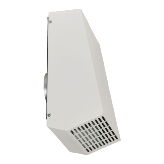
- Page 1 Installation, Operation and Maintenance instruction RVF wall fan AC/EC...
-
Page 2: Table Of Contents
Table of content 1 Introduction ............1 12.3.2 Wiring diagrams for EC fans .... 12 12.3.3 Wiring diagrams for speed Product description ........1 controller for AC motors ....13 Intended use ..........1 12.3.4 Wiring diagrams for speed Document description........1 controllers for EC motors.... -
Page 3: Introduction
The product is used for extraction of clean or contaminated Speak to Systemair for more information on how to install the air with a maximum temperature of between 60-70 °C for dif- product in different installation locations. -
Page 4: Type Designation
• The product is used together with accessories that are not original accessories from Systemair. • The product is used without motor protection. Use a mobile device to scan the scannable code and go to the Systemair documentation portal for more documentation and document translations. -
Page 5: Personal Protective Equipment
–10 and +30 °C. A stable ambient • Sound levels exceeding 70 dB(A) may occur depending temperature prevents damage from condensation. on model and size. Visit www.systemair.com for more de- tailed information about your product. • Keep the product in storage for maximum 1 year. -
Page 6: Installation
Connect the product (E) to the duct. Use the fast clamp of the product to attach the duct to the product. Systemair recommends to use a FK fast clamp to attach the duct to the product. • Make sure that you have the necessary installation The FK fast clamp are available as an accessory. -
Page 7: Electrical Connection
To install motor protection for Electrical connection AC motors To do before the electrical • If the product has an built in motor protection, reset by dis- connection connecting the product from power for 60 seconds. • If the motor has temperature monitors such as thermal •... -
Page 8: Commissioning
To start a product with an EC motor The commissioning report is found at www.systemair.com. Make sure that the 0–10 V signal is set to “0” with the speed controller. To do before the... -
Page 9: Maintenance
• For information about spare parts, send an e-mail to Caution support@systemair.com. • Do not clean the product with a high- • For more information about spare parts, contact Systemair pressure washer. support. • Do not clean the product with steel •... -
Page 10: Troubleshooting
Troubleshooting Note: If you cannot find a solution to your problem in this section, speak to Systemair technical support. Problem Cause Solution The fan impeller is not correctly Speak to Systemair technical support. balanced. There is dirt on the fan impeller. - Page 11 This is not applicable for EC motors or 3–phase AC motors. There is blockage in the motor. Speak to Systemair technical support. Defective motor winding. If it is possible, measure the resistance to do a check of the motor winding.
-
Page 12: Disposal
For warranty claims, send a written maintenance plan and product or the packaging of the product shows that this the commissioning report to Systemair. The warranty is only product is not domestic waste. The product must be recycled applicable for these conditions: at an approved disposal location for electrical and electronic •... -
Page 13: Technical Data
12.1 Technical data overview Maximum temperature of transported air, °C Maximum ambient temperature, °C Refer to the data sheet in the online catalogue at www.systemair.com. Sound pressure, dB Corrosion class IP class Voltage, current, frequency, enclosure Refer to the name plate. Refer to 1.5 Name plate page 1... -
Page 14: Wiring Diagrams
Wiring diagrams for EC fans Note: An internal potentiometer is installed on the terminal block from the factory. Remove the internal potentiometer when you use an external speed controller for the EC fan. RVF fans 1–phase 230 V RVF 100 EC... -
Page 15: Wiring Diagrams For Speed Controller For Ac Motors
12.3.3 Wiring diagrams for speed controller for AC motors Note: The selection of electrical accessories must be done in line with the technical parameters of the product. Manual 5-step transformer. RE 1,5 RE 3 RE 5 RE 7 Relay connection. There is always 230 V between ~ and N when the transformer knob is in one of the positions 1–5. Mains supply C. - Page 16 RTRE Manual 5-step transformer with motor protection. RTRE 1,5 RTRE 3 RTRE 5 RTRE 7 RTRE 12 Relay connection. There is always 230 V between ~ and N when the transformer knob is in one of the positions 1–5. Mains supply C.
- Page 17 Contact rating, maximum AC 250 V/2 A Mains supply, 1–phase 208...277 V, 50/60 Hz C. Motor with internal thermal contacts D. OFF/ON RTRD A 3-phase transformer that controls the fan speed by altering the supply voltage in five fixed steps. The steps are adjusted by using the control knob on the front of the unit.
-
Page 18: Wiring Diagrams For Speed Controllers For Ec Motors
RTRDU Manual 5–step transformer with motor protection — a 3–phase transformer that controls the fan speed by altering the supply voltage in five fixed steps. The steps are adjusted by using the control knob on the front of the unit. RTRDU FS FS TB TB... - Page 19 MTP 20 MTP 20 1/Vdc+ +10V 4/Vout 0...10V 2/Vdc- 3/Vout- EC-Basic EC-Basic 1/IN Vac 230V AC 2/IN Vac +10V 4/Out 0...10V 5/GND MTV–1/10 MTV 1/010 1/IN Vac 230V AC 2/IN Vac +10V 4/Out+ 0...10V 5/Out- S-5EC/FRQ MTP 10 +10V 0...10V EC-Vent optional IN/RPM...
-
Page 20: Wiring Diagrams For On/Off Controls For Ec Motors
12.3.5 Wiring diagrams for ON/OFF controls for EC motors CO2RT-R(-D) Supply +10V 24V AC Neutral 0...10V Common Relay NO Relay NC Din1 IR24–P +10V 24V AC or DC Neutral 0...10V Common Relay NO Relay NC Din1 12.3.6 Wiring diagrams for demand control for EC motors EC Basic EC Basic-T for temperature control EC-Basic... - Page 21 EC-Vent Demand control for up to 5 external sensors, 2 fans, damp- ers, heaters and coolers. The EC vent system has 2 units. The control board (CB) and the room unit (RU). Connect the fan to the control board and optional IN/RPM TACH...
- Page 22 Control Board (CB) ALARM FAN OUT3 OUT2 OUT1 DEBUG PT1000 +24VDC PT1000 Y +0-10V PT1000 Br + 24VDC N out N in L out L in Mains supply, 230 V 1~AC (10 A) Analogue sensor (for example, pressure sensor) C. Analogue sensor (for example, pressure sensor type PT1000) D.
- Page 23 MM6-24/D output signal selector Compares signals from connected inputs and transfers the signal to the control output. Input 1 0...10 V Input 2 0...10 V Input 3 0...10 V Input 4 0...10 V Input 5 0...10 V Input 6 0...10 V System neutral Mains supply...
-
Page 24: Accessory Overview
Accessory overview LDC: Silencer FK fast clamp Balance-E extract air diffuser RSK: Back draft damper Note: For more information about accessories, refer to www.systemair.com or speak to Systemair technical support. -
Page 25: Eu Declaration Of Conformity
EU Declaration of Conformity We, the manufacturer Manufacturer Systemair Sverige AB Address Industrivägen 3 739 30 Skinnskatteberg Sweden declare under our sole responsibility that the products Type/Model Identification Serial numbers dating from 2022 and onwards fulfils the relevant provisions of following directives and... -
Page 26: Declaration Of Conformity
UK Declaration of Conformity We, the manufacturer Manufacturer Systemair Sverige AB Address Industrivägen 3 SE-73930 Skinskatteberg Sweden declare under our sole responsibility that the products Type/Model Identification Serial numbers dating from 2022 and onwards fulfils the relevant provisions of following directives and... - Page 28 © Copyright Systemair AB All rights reserved Systemair AB reserves the rights to alter their products without notice. This also applies to products already ordered, as long as it does not affect the previously agreed specifications. Original instructions 2022-06-07...
Need help?
Do you have a question about the RVF 100 and is the answer not in the manual?
Questions and answers