Advertisement
Quick Links
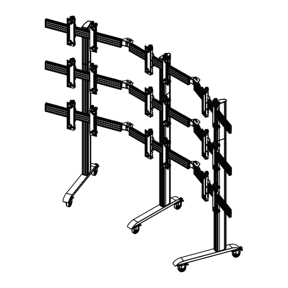
BT8374
UNIVERSAL CURVED mobile
VIDEOWALL STAND
INSTALLATION GUIDE
SPECIFICATIONS
• Recommended screen size: 39"- 70"
• Max weight per screen: 50kg (110lbs)
• Suitable for landscape or portrait mounting
• Angle adjustment range: +/- 45° between screens
• Safety screws help prevent unauthorised removal of screens
• All mounting hardware included
Note: This assembly manual covers di erent installations. Some
parts or procedures shown may not be required for installation.
Please refer to page 5
for VESA® xings
www.btechavmounts.com
TM
PER SCREEN
Advertisement

Subscribe to Our Youtube Channel
Related Manuals for BTECH BT8374


Summary of Contents for BTECH BT8374
- Page 1 BT8374 UNIVERSAL CURVED mobile VIDEOWALL STAND INSTALLATION GUIDE SPECIFICATIONS • Recommended screen size: 39”- 70" • Max weight per screen: 50kg (110lbs) • Suitable for landscape or portrait mounting • Angle adjustment range: +/- 45° between screens • Safety screws help prevent unauthorised removal of screens •...
-
Page 2: Table Of Contents
CONTENTS Installation Safety Notes........................Parts List..............................Typical Installation..........................Installation Notes........................... Installation Instructions........................Product Dimensions........................... B-Tech Contact Details........................INSTALLATION & OPERATING SAFETY INSTRUCTIONS CAUTION: This mount is intended for use only with the maximum weights indicated. Use with equipment heavier than the maximum indicated may result in instability causing possible injury. - Page 3 B-Tech AV Mounts 建议本产品由专业AV安装人员或其他合格人员安装。 B-Tech AV Mounts 及它的代理商、经销商不对 由于不恰当的安装而造成的损失或伤害负责。 本产品必须安装在合适的架构上,并仅用于不超过所标示的最大承重。 Společnost B-Tech AV Mounts doporučuje provést instalaci tohoto produktu instalátora AV či jinak způsobilé osoby. Společnost B-Tech AV Mounts, její distributoři a prodejci nenesou prostřednictvím odborného odpov ědnost za škody nebo zranění...
-
Page 4: Parts List
BT8374 PARTS LIST Due to the multiple installations available the quantity for each option below is dependent on the mount ordered. All these components can be moved or carried by manpower. Please be careful to avoid injury when PLEASE KEEP THIS FOR FUTURE REFERENCE handling these components before &... - Page 5 ANGLE BT8390-AAC ADJUSTMENT CONNECTOR ITEM PART NAME PER PACK ANGLE CONNECTOR M8 x 16mm SCREW M8 WASHER M8 x 12mm SCREW M8 SLIDING NUT 5AF HEX KEY SPACER BT8390-SP PART NAME ITEM PER PACK SPACER INTERFACE KIT Screen Interface Arms BT8390-VESA400MAP BT8390-VESA400MAF PART NAME...
-
Page 6: Typical Installation
VESA 400 Micro-Adjustment arms REQUIRED Crosshead screwdriver Spanner Knife/Cutter Level (Optional) BT8374 MAX LOAD CONFIGURATIONS INSTALLATION notes MAX. COLUMN HEIGHT 3.6M FLOORSTAND STABILITY Note: Screen weight must be evenly spread up the vertical column NOTE: Larger installs may require the use of a BT8380-WTB •... - Page 7 OPTIONAL EXTENDING THE COLUMNS EXTEND VERTICAL COLUMNS i. Insert item B7 halfway into the non-threaded end of item B1. The two joining bars with item B8 go in the front of the column and the 2 joining bars with item B9 go in the back. IMPORTANT: Joining bars should be inserted into the non-threaded end of...
-
Page 8: Installation Instructions
INSTALLATION INSTRUCTIONS ATTACH JOINING PLATES TO COLUMNS i. On item C1, assemble 4x item C3 to item C2. ii. Lay the column on the oor and t item C1 to item B1. IMPORTANT: Make sure the end with M8 threads are at the bottom of the columns. - Page 9 iii. Use item F1 to set the distance between items C1 on item B1 according to the screen size. Once set, tighten item C3. ADJUSTMENT KNOB Leave at least a 5mm gap at top of column for item B2.
- Page 10 INSERT SLIDING NUTS INTO MOUNTING RAILS i. Lay the rail on the oor and for each item C1 used, insert 4x item C2 into item D1. Two in the 2nd channel and two in the bottom channel. ii. To attach item E1 to the rail, insert 4x item E5 into the end of item D1. Two in each centre channel. Angle Adjustment Connector Column / Joining Plate Assembly...
- Page 11 CONNECT RAILS TOGETHER USING THE ANGLE ADJUSTMENT i. Assemble items E2 & E3 to item E1. Do not fully tighten the screws and washers. ii. With the rails at on the oor, x item E1 to 2 x item D1 using items E3, E4 & E5. Make sure all rails are xed using the same positions on item E1*.
- Page 12 ATTACH COLUMNS TO RAILS On the oor, place item B1 onto item D1. Attach item C1 to item D1 by fastening item C3 into the inserted items C2. Note: To ensure straight assembly of item B1 make sure the distance of items C1 to the end of item D1 are set the same on each rail.
- Page 13 ASSEMBLE BASES TO COLUMNS i. For a mobile application, unscrew item A2 on item A1 and replace with item A5 before attaching the base to the columns. Note: Ensure castors are set on the braked position for assembly. ii. On the oor, attach item A1 to the columns item C1 using items A2, A3 & A4. Note: Once bases are xed, return stand to upright position.
- Page 14 FIX ANGLE Set the angle required on item E1 and fully tighten all screws with item E6.
- Page 15 ATTACH INTERFACE ARMS TO SCREEN (BT8390-VESA400MAF ARMS) Attach items G1 & G2 to the back of the screens using items A-F. Note: Ensure the arms are SCREEN FIXING KIT facing the correct way round and the same holes are used on both arms. Note: Use spacers for screens with recessed xings SCREEN SCREEN...
- Page 16 ATTACH POP-OUT INTERFACE ARMS TO SCREENS (BT8390-VESA400MAP ARMS) Attach items G1 & G2 to the back of the screens using items A-F. Note: Ensure the arms are facing the correct way round and the same holes are used on both arms. SCREEN SCREEN RECESS...
- Page 17 BT8390-VESA400MAP ARMS ii. Connect interface arms with the adjustable brace. Extend item G3 and x at desired length by tightening the 2 screws. Note: Item G3 is only suitable for horizontal VESA xings between 400 - 600mm. The 3 notches show the position for interface xings at 400mm, 500mm and 600mm. For screens with interface holes 600mm apart, extend brace to the 600 settting.
- Page 18 HOOK SCREEN ONTO THE STAND i. Hook the rst screen centrally onto the bottom rail and align screen with the horizontal centre of the stand. Note: Ensure castors are set to the braked position when screen mounting. ii. Align the screen to the oor using the height adjustment (Y Axis) knobs - See page 20. Note: If mounting 3 or more screens across, mount the rst screen centrally onto the bottom rail.
- Page 19 MOUNT SCREENS ONTO THE STAND Hook the remaining screens onto the stand. Note: A 1mm gap between screens should be maintained.
- Page 20 ALIGN SCREENS USING MICRO-ADJUSTMENT i. Align the screen to the oor using the height adjustment (Y Axis) knobs. ii. Use the depth adjustment (Z Axis) knobs to ensure the screen is perpendicular with the oor to ensure that each corner of the screen is aligned evenly. Note: Micro-adjust top row rst and work down row by row.
- Page 21 SECURE SCREENS Once screens are aligned, tighten the safety screws on the bottom of items G1 & G2 SAFETY SCREW BT8390-VESA400MAP SERVICING SCREENS (POP-OUT ARMS ONLY) Items G1 & G2 Push centrally at the left and right of the screen popped-out to pop-out the mount.
- Page 22 ADD END CAPS & CABLE MANAGEMENT COVERS i. Once all the screens and power cables are connected and if possible routed down the back of item B1, partially clip on items B3 (this allows easy removal if more cables need adding).
-
Page 23: Product Dimensions
BT8374 DIMENSIONS Depending on installation requirements, the BT8374 Curved Mobile Videowall Stand will feature a selection of the following products. PLEASE KEEP THIS FOR FUTURE REFERENCE +/- 45° INTERFACE ARMS BASE BT8380-BASE BT8390-VESA400MAF 8.4mm 6.4mm 950mm 222mm Ø100mm 793.5mm 30mm 86mm 49.7mm... -
Page 24: B-Tech Contact Details
All other brands and product names are trademarks of their respective owners. Photographs are for illustrative purposes only. E&OE. Manufactured by: B-Tech International Ltd Bennett House, Long March, Daventry, Northamptonshire, NN11 4NR, UK B-Tech Pro-AV BVBA Brixtonlaan 32, Zaventem 1930, Brussels, Belgium AMA-BT8374-V1.2-1021-BTECH MADE IN VIETNAM For More Information Visit www.btechavmounts.com...
Need help?
Do you have a question about the BT8374 and is the answer not in the manual?
Questions and answers