Advertisement
Quick Links
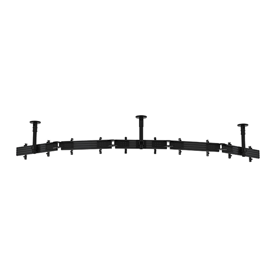
BT8333
CURVED UNIVERSAL CEILING MOUNTED
MENU BOARD MOUNTING SYSTEM
INSTALLATION GUIDE
SPECIFICATIONS
• Recommended screen size: 32"- 70"
• Max weight per screen: 50kg (110lbs)
• Suitable for landscape or portrait mounting
• Angle adjustment range: +/- 45° between screens
• Safety screws help prevent unauthorised removal of screens
• All mounting hardware included
Note: This assembly manual covers di erent installations. Some
parts or procedures shown may not be required for installation.
Please refer to page 5
for VESA® xings
www.btechavmounts.com
TM
PER SCREEN
Advertisement

Subscribe to Our Youtube Channel
Related Manuals for BTECH BT8333


Summary of Contents for BTECH BT8333
- Page 1 BT8333 CURVED UNIVERSAL CEILING MOUNTED MENU BOARD MOUNTING SYSTEM INSTALLATION GUIDE SPECIFICATIONS • Recommended screen size: 32”- 70" • Max weight per screen: 50kg (110lbs) • Suitable for landscape or portrait mounting • Angle adjustment range: +/- 45° between screens •...
- Page 2 CONTENTS Installation Safety Notes........................Parts List..............................Typical Installation..........................Installation Instructions........................Product Dimensions..........................B-Tech Contact Details........................INSTALLATION & OPERATING SAFETY INSTRUCTIONS CAUTION: This mount is intended for use only with the maximum weights indicated. Use with equipment heavier than the maximum indicated may result in instability causing possible injury.
- Page 4 BT8333 PARTS LIST Due to the multiple installations available the quantity for each option below is dependent on the mount ordered. All these components can be moved or carried by manpower. Please be careful to avoid injury when PLEASE KEEP THIS FOR FUTURE REFERENCE handling these components before &...
- Page 5 ANGLE BT8390-AAC ADJUSTMENT CONNECTOR ITEM PART NAME PER PACK ANGLE CONNECTOR M8 x 16mm SCREW M8 WASHER M8 x 12mm SCREW M8 SLIDING NUT 5AF HEX KEY BT7824 OPTIONAL POLE EXTENSION KIT ITEM PART NAME PER PACK BT7823 EXTERNAL JOINER M8 GRUB SCREW PART NAME ITEM...
-
Page 6: Typical Installation
TYPICAL INSTALLATION INSTALLATION TOOLS REQUIRED 3 x 1 Curved Menu Board Installation with VESA 400 Fixed Arms Crosshead Drill Pencil screwdriver Level (Optional) CABLE CABLE MANAGEMENT Route any screen cables through the CEILING bottom of the pole and out through CABLE the top of the mount or use the cable management hole on the back of item A1. - Page 7 OPTIONAL COMBINING THE EXTENSION POLES BT7823 INTERNAL POLE JOINER iii. Slide item B1 onto the bottom of item G1 and i. Insert item G1 into the bottom of item B1, lining align the bottom screw holes on item G1 up the top screw holes on item G1 with the holes with the holes on the pole.
-
Page 8: Installation Instructions
INSTALLATION INSTRUCTIONS ASSEMBLE COLLARS ONTO RAILS Assembly using 2 single collars i. Attach item C1 onto item D1. Note: Ensure items C2 are positioned on the back of item C1. ii. Insert 2x item D2 into the top channel of item E1 and 2x item D2 in the bottom channel. - Page 9 FIX ANGLE CONNECTORS TO MOUNTING RAILS i. Insert 4 x item F5 into the end of item E1 (2 in each centre channel). ii. Assemble items F2 & F3 to item F1. Note: Do not fully tighten the screws and washers.
- Page 10 iii. With the rails at on the oor, connect item F1 to 2x item E1 using items F3, F4 & F5. Note: Make sure all rails are xed using the same positions on item F1*. *Note: The rail xing positions used on item F1 are dependent on the size of screens being used. For help with the rail xing postion contact: technical@btechavmounts.co.uk...
- Page 11 FIX ANGLE Set the angle required on item F1 and fully tighten all screws using item F6.
- Page 12 CEILING PLATE FIXING DIMENSIONS MOUNT CEILING PLATES Fix item A1 to the ceiling using suitable xings (not supplied). 10.5mm CEILING Optional depending on the type 120mm of ceiling Note: Space item A1 the same distance apart as item C1 on item E1. CABLE MANAGEMENT HOLE...
- Page 13 FIX RAILS TO POLES i. Slide items C1 & E1 onto item B1, aligning the pole hole with the collar hole. POLE HOLE COLLAR HOLE ii. Fasten item C2. iii. Insert item C3 through item C1 & B1 securing the rail. iv.
- Page 14 ATTACH INTERFACE ARMS TO SCREEN Fix items H1 & H2 to the rear of the screen using items A-M. Note: Ensure the arms are A. FIXED ARMS facing the correct way round and the same holes are used on both arms. SCREEN FIXING KIT SCREEN...
- Page 15 C. MICRO-ADJUSTMENT ARMS Fix items H1 & H2 to the rear of the screen using items D-N. Note: Ensure the arms are facing the correct way SCREEN FIXING KIT round and the same holes are used on both arms. Note: Use spacers for screens with recessed xings SCREEN SCREEN OPTIONAL ADAPTOR ARMS...
- Page 16 HOOK SCREENS ONTO MOUNTING RAIL i. Hook rst screen onto the centre rail. Note: If mounting 3 or more screens across, mount the rst screen centrally onto the middle rail. Z AXIS Y AXIS KNOB SCREEN KNOB Z AXIS KNOB ii.
- Page 17 SCREEN ALIGNMENT USING MICRO-ADJUSTMENT Y AXIS KNOB (Only available with BT8390-VESA400MAF*) Z AXIS i. Use the Y & Z KNOB micro-adjustment knobs on items H1 & H2 to align screens. *For Fixed and Tilt arms use the height adjustment screws on top of items H1 &...
-
Page 18: Ceiling Mount
BT8333 DIMENSIONS Depending on installation requirements, the BT8333 Curved Menu Board Ceiling Mounting Kit will feature a selection of the following products. PLEASE KEEP THIS FOR FUTURE REFERENCE CEILING MOUNT EXTENSION POLE BT7822 BT7850 REAR VIEW 35.7mm POLE ASSEMBLY EXAMPLE... - Page 19 BT8333 DIMENSIONS Depending on installation requirements, the BT8333 Curved Menu Board Ceiling Mounting Kit will feature a selection of the following products. PLEASE KEEP THIS FOR FUTURE REFERENCE INTERFACE ARMS BT8390-VESA200F BT8390-VESA200T BT8390-VESA400F 20° 15° 10° 45.2mm 28mm 28mm 75mm...
- Page 20 All other brands and product names are trademarks of their respective owners. Photographs are for illustrative purposes only. E&OE. Manufactured by: B-Tech International Ltd Bennett House, Long March, Daventry, Northamptonshire, NN11 4NR, UK B-Tech Pro-AV BVBA Brixtonlaan 32, Zaventem 1930, Brussels, Belgium AMA-BT8333-V1.2-0721-BTECH MADE IN VIETNAM For More Information Visit www.btechavmounts.com...
Need help?
Do you have a question about the BT8333 and is the answer not in the manual?
Questions and answers