Ossila Solar Cell I-V Test System User Manual
Test system
Hide thumbs
Also See for Solar Cell I-V Test System:
- User manual (25 pages) ,
- User manual (30 pages) ,
- User manual (30 pages)

Related Manuals for Ossila Solar Cell I-V Test System


Summary of Contents for Ossila Solar Cell I-V Test System
- Page 1 Manual version: 2.0.L Product code: T2002 Product Version: 2.0 Software version: 1.6...
-
Page 2: Table Of Contents
Solar Cell I-V Test System (Manual) User Manual Contents Overview ............................... 2 EU Declaration of Conformity (DoC) ......................3 Safety................................6 Use of Equipment ................................6 Hazard Icons .................................. 6 General Hazards ................................6 Power Cord Safety ................................. 7 Servicing ..................................7 Health and Safety –... -
Page 3: Overview
User Manual Overview The Ossila Solar Cell I-V Test System is a low-cost solution for reliable current-voltage characterisation of solar cells. The system is controlled by specially designed software which can perform multiple I-V measurements, determine key metrics of solar cells, and measure these properties over long periods of time. -
Page 4: Eu Declaration Of Conformity (Doc)
System – No Test Board (T2002D2) Serial number: T2002A2-xxxx, T2002B2-xxxx, T2002D2-xxxx, T2002E2-xxxx. Object of declaration: Solar Cell I-V Test System – Manual (T2002A2/T2002B2/T2002E2), Solar Cell I-V Test System – No Test Board (T2002D2) The object of declaration described above is in conformity with the... - Page 5 Декларация за съответствие на ЕС Производител: Ossila BV, Biopartner 3 building, Galileiweg 8, 2333 BD Leiden, NL. Декларира с цялата си отговорност, че посоченото оборудване съответства на приложимото законодателство на ЕС за хармонизиране, посочено на предходната(-ите) страница(-и) на настоящия документ.
- Page 6 User Manual [Magyar] EU-s megfelelőségi nyilatkozat Gyártó: Ossila BV, Biopartner 3 building, Galileiweg 8, 2333 BD Leiden, NL. Kizárólagos felelösségünk mellett kijelentjük, hogy a felsorolt eszköz megfelel az ezen dokumentum előző oldalán/oldalain található EU-s összehangolt jogszabályok vonatkozó rendelkezéseinek. [Nederlands] EU-Conformiteitsverklaring Fabrikant: Ossila BV, Biopartner 3 building, Galileiweg 8, 2333 BD Leiden, NL.
-
Page 7: Safety
• input while not powered. Use of Equipment The Ossila Solar Cell I-V Test System (Manual) is designed to be used as instructed. It is intended for use under the following conditions: Indoors in a laboratory environment (Pollution Degree 2). -
Page 8: Power Cord Safety
To facilitate disconnect, make sure the power outlet for this cord is readily accessible to the operator. Servicing If servicing is required, please return the unit to Ossila Ltd. The warranty will be invalidated if: Modification or service has taken place by anyone other than an Ossila engineer. •... -
Page 9: Requirements
Solar Cell I-V Test System (Manual) User Manual Requirements Table 4.1 details the power requirements for the Solar Cell I-V Test System, and the minimum computer specifications for the Ossila Solar Cell I-V software. Table 4.1. Solar Cell I-V Test System requirements. -
Page 10: Specifications
Solar Cell I-V Test System (Manual) User Manual Specifications The Solar Cell I-V Test System (Manual) specifications are shown in Table 6.1. Table 6.1. Ossila Solar Cell I-V Test System (Manual) specifications. Voltage range ±10 mV to ±10 V Voltage accuracy ±10 mV offset... -
Page 11: System Components
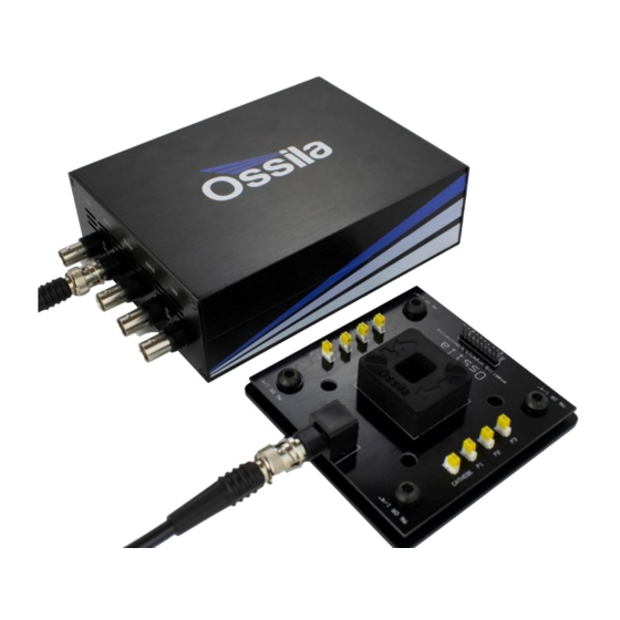
User Manual System Components The Solar Cell I-V Test System (Manual) is comprised of 3 items: the Source Measure Unit (Figure 7.1), Push-Fit Test Board (Figure 7.2), and the Ossila I-V Curve software (Figure 7.3). Figure 7.1. Source Measure Unit. -
Page 12: Installation
2. Connect the 24 VDC power adaptor to the power socket on the rear of the unit. 3. Connect the unit to your PC using the provided USB-B cable, or an Ethernet cable if preferred. Note: The Ossila Solar Cell I-V software can also be downloaded from ossila.com/pages/software-drivers Operation Measurement Types The Solar Cell I-V software can perform 3 different types of measurements. - Page 13 Between I-V measurements, the solar cell can be held at short-circuit, open-circuit, or maximum power. Figure 9.2. Ossila Solar Cell I-V software: The Lifetime tab. 9.1.3 Stabilised Current The Stabilised Current tab lets you measure the evolution of the photogenerated current at specific voltages.
-
Page 14: Quick Start Guide
Figure 9.3. Ossila Solar Cell I-V software: The Stabilised Current tab. Quick Start Guide 1. Start the Ossila Solar Cell I-V software. The window shown in Figure 9.1will open. 2. Choose a measurement type as described in Section 9.1. 3. Place your sample in the device holder. - Page 15 Solar Cell I-V Test System (Manual) User Manual 9.3.1 System Settings Figure 9.4. System settings. (I) System Address Select the COM port or IP address of the connected unit you intend to use (USB and • Ethernet connection respectively). This box will be populated automatically with the addresses of any units connected to the computer.
- Page 16 Solar Cell I-V Test System (Manual) User Manual Table 9.1. Maximum current and accuracy for the different range settings for the Ossila Solar Cell I-V Test System. Maximum Current Accuracy Precision Resolution ±200 mA ±500 μA 10 μA 1 μA ±20 mA...
-
Page 17: Characterisation Settings
Solar Cell I-V Test System (Manual) User Manual (IV) Inverted Device Set whether the device to be measured is inverted. • This option should be on if the anode of your device connects to the ‘cathode’ pins in the device holder. -
Page 18: Lifetime Settings
Solar Cell I-V Test System (Manual) User Manual (VI) Hysteresis I-V This option performs a reverse current-voltage measurement after the forward current- • voltage measurement has completed. This reverses the set start and end voltages and uses the same voltage increment and settle time as the forward measurement. - Page 19 Solar Cell I-V Test System (Manual) User Manual (VI) Hysteresis I-V Set whether to perform a reverse current-voltage measurement after the forward current- • voltage measurement has completed. This reverses the set ‘start’ and ‘end’ voltages and uses the same voltage increment and settle time as the forward measurement.
-
Page 20: Stabilised Current Settings
Solar Cell I-V Test System (Manual) User Manual Stabilised Current Settings 9.6.1 Measurement Settings Figure 9.9. Experimental Parameters settings for the Stabilised Current Output. (I) Voltage Set the voltage to apply to the sample for the measurement. • This can be set between -10 V and +10 V. -
Page 21: Saving And Loading Settings
Solar Cell I-V Test System (Manual) User Manual Saving and Loading Settings Figure 9.10. Controls for saving and loading settings profiles. (I) Save Settings Saves the current settings as a profile that can be loaded quickly for use at another time. - Page 22 Solar Cell I-V Test System (Manual) User Manual Warning: Automatic saving can be turned off for lifetime measurements. However, manual saving is unavailable for lifetime measurements, so you will not be able to save your data if it is turned off.
-
Page 23: Controls
Solar Cell I-V Test System (Manual) User Manual Figure 9.12. Characterisation save data format. Figure 9.13. Stabilised Current Output save data format. Figure 9.14. Solar Lifetime Measurement save data. Controls Figure 9.15. Controls for the measurements. (I) Measure Clicking this button will start the measurement using the chosen settings. -
Page 24: Plot Controls
Solar Cell I-V Test System (Manual) User Manual 9.10 Plot Controls (I) Position Readout Whilst the mouse cursor is over the plot in the Characterisation and Stabilised Current tabs, the x and y position of its location are displayed in the bottom-right of the plot, as shown in Figure 9.16. -
Page 25: Test Device
Solar Cell I-V Test System (Manual) User Manual 10. Test Device The system is shipped with a test device with 100 kΩ resistors that can be used to check the calibration of the system. They are arranged in the geometry of the substrate pixels, and the appearance of the test device will depend on the substrate system being used (Figure 10.1). - Page 26 Solar Cell I-V Test System (Manual) User Manual Resistance can be calculated using: R = V / I II. For the 200 mA current range the calculated resistance should be between 98 and 102 kΩ (within 2% of the resistor value).
-
Page 27: Troubleshooting
11. Troubleshooting Most of the issues that may arise will be detailed here. However, if you encounter any issues that aren’t in this list, please contact us by email at info@ossila.com, and we will respond as soon as possible. 11.1 Installation and Setup... -
Page 28: Error Messages And Warnings
Solar Cell I-V Test System (Manual) User Manual 11.2 Error Messages and Warnings Message Description Current compliance reached The measured current is greater than the set current limit. Error communicating with The software is unable to connect to the system. -
Page 29: Related Products
Solar Cell I-V Test System (Manual) User Manual 12. Related Products 12.1 Related Consumables ITO Coated Substrates Flat Tip Tweezers Our range of ITO substrates for Provides a good substrate grip OPV, OLED, and sensing without scratching. applications. Product codes: S111 / S101 / S211 / S281 / S171...
Need help?
Do you have a question about the Solar Cell I-V Test System and is the answer not in the manual?
Questions and answers