Ossila Solar Cell I-V Test System User Manual
Hide thumbs
Also See for Solar Cell I-V Test System:
- User manual (25 pages) ,
- User manual (30 pages) ,
- User manual (30 pages)

Subscribe to Our Youtube Channel
Related Manuals for Ossila Solar Cell I-V Test System


Summary of Contents for Ossila Solar Cell I-V Test System
- Page 1 Solar Cell I-V Test System (Manual) User Manual Manual version: 2.0.I Product code: T2002 Product Version 2.0 Software version: 1.4 enabling materials science Ossila.com...
-
Page 3: Table Of Contents
Solar Cell I-V Test System (Manual) User Manual Contents Overview ..............................2 EU Declaration of Conformity (DoC) ......................3 Safety ................................6 Use of Equipment ................................6 Hazard Icons ................................... 6 General Hazards ................................6 Power Cord Safety ................................. 6 Servicing.................................. -
Page 4: Overview
User Manual Overview The Ossila Solar Cell I-V Test System is a low-cost solution for reliable current-voltage characterisation of solar cells. The system is controlled by specially designed software which can perform multiple I-V measurements, determine key metrics of solar cells, and measure these properties over long periods of time. -
Page 5: Eu Declaration Of Conformity (Doc)
System – No Test Board (T2002D2) Serial number: T2002A2-xxxx, T2002B2-xxxx, T2002D2-xxxx, T2002E2-xxxx. Object of declaration Solar Cell I-V Test System – Manual (T2002A2/T2002B2/T2002E2), Solar Cell I-V Test System – No Test Board (T2002D2) The object of declaration described above is in conformity with... - Page 6 EU-harmoniseringslovgivning, på den/de foregående side(r) i dette dokument. [Deutsch] EU-Konformitätserklärung Hersteller: Ossila BV, Biopartner 3 building, Galileiweg 8, 2333 BD Leiden, NL. erklären in alleiniger Verantwortung, dass das aufgeführte Gerät konform der relevanten EU-Harmonisierungsgesetzgebung vorangegangenen Seiten dieses Dokuments ist.
- Page 7 Solar Cell I-V Test System (Manual) User Manual [Slovenščina] Izjava EU o skladnosti Proizvajalec: Ossila BV, Biopartner 3 building, Galileiweg 8, 2333 BD Leiden, NL. strani/prejšnjih s polno odgovornostjo izjavlja, da je navedena oprema skladna z veljavno uskladitveno zakonodajo navedeno prejšnji...
-
Page 8: Safety
Solar Cell I-V Test System (Manual) User Manual Safety Use of Equipment The Ossila Solar Cell I-V Test System (Manual) is designed to be used as instructed. It is intended for use under the following conditions: Indoors in a laboratory environment (Pollution Degree 2) •... -
Page 9: Servicing
Solar Cell I-V Test System (Manual) User Manual Servicing If servicing is required, please return the unit to Ossila Ltd. The warranty will be invalidated if: Modification or service has taken place by anyone other than an Ossila engineer. •... -
Page 10: Requirements
1680 x 1050 Connectivity USB 2.0 or Ethernet Unpacking Packing List The standard items included with the Ossila Solar Cell I-V Test System (Manual) are: Ossila Solar Cell I-V Test System and Test Board. • 24 VDC power adapter. •... -
Page 11: Specifications
Solar Cell I-V Test System (Manual) User Manual Specifications The Solar Cell I-V Test System (Manual) specifications are shown in Table 6.1. Table 6.1. Ossila Solar Cell I-V Test System (Manual) specifications. Voltage range ±333 µV to ±10 V Current range ±10 nA to ±200 mA... -
Page 12: System Components
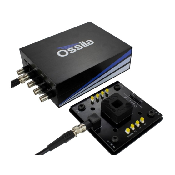
User Manual System Components The Solar Cell I-V Test System (Manual) is comprised of 3 items: the Source Measure Unit (Figure 7.1), Push-Fit Test Board (Figure 7.2), and the Ossila I-V Curve software (Figure 7.3). Figure 7.1. Source Measure Unit. -
Page 13: Installation
2. Connect the 24 VDC power adaptor to the power socket on the rear of the unit. 3. Connect the unit to your PC using the provided USB-B cable, or an Ethernet cable if preferred. Note: The Ossila Solar Cell I-V software and can also be downloaded from https://www.ossila.com/pages/software-drivers Operation Measurement Types The Solar Cell I-V software can perform 3 different types of measurements. - Page 14 Between I-V measurements, the solar cell can be held at short-circuit, open-circuit, or maximum power. Figure 9.2. Ossila Solar Cell I-V software: The Lifetime tab. 9.1.3 Stabilised Current The Stabilised Current tab lets you measure the evolution of the photogenerated current at specific voltages.
-
Page 15: Quick Start Guide
Figure 9.3. Ossila Solar Cell I-V software: The Stabilised Current tab. Quick Start Guide 1. Start the Ossila Solar Cell I-V software. The window shown in Figure 9.1 will open. 2. Choose a measurement type as described in Section 9.1. - Page 16 Solar Cell I-V Test System (Manual) User Manual 9.3.1 System Settings Figure 9.4. System settings. (I) System Address Select the COM port or IP address of the connected unit you intend to use (USB and • Ethernet connection respectively). This box will be populated automatically with the addresses of any units connected to the computer.
- Page 17 Solar Cell I-V Test System (Manual) User Manual Table 9.1. Maximum current and accuracy for the different range settings for the Ossila Solar Cell I-V Test System. Maximum Current Accuracy ±200 mA ±500 μA ±20 mA ±10 μA ±2000 μA ±1 µA...
-
Page 18: Characterisation Settings
Solar Cell I-V Test System (Manual) User Manual (IV) Inverted Device Set whether the device to be measured is inverted. • This option should be on if the anode of your device connects to the ‘cathode’ pins in the device holder. -
Page 19: Lifetime Settings
Solar Cell I-V Test System (Manual) User Manual (VI) Hysteresis I-V This option performs a reverse current-voltage measurement after the forward current- • voltage measurement has completed. This reverses the set start and end voltages and uses the same voltage increment and settle time as the forward measurement. - Page 20 Solar Cell I-V Test System (Manual) User Manual (VI) Hysteresis I-V Set whether to perform a reverse current-voltage measurement after the forward current- • voltage measurement has completed. This reverses the set ‘start’ and ‘end’ voltages and uses the same voltage increment and settle time as the forward measurement.
-
Page 21: Stabilised Current Settings
Solar Cell I-V Test System (Manual) User Manual Stabilised Current Settings 9.6.1 Measurement Settings Figure 9.9. Experimental Parameters settings for the Stabilised Current Output. (I) Voltage Set the voltage to apply to the sample for the measurement. • This can be set between -10 V and +10 V. -
Page 22: Saving And Loading Settings
Solar Cell I-V Test System (Manual) User Manual Saving and Loading Settings Figure 9.10. Controls for saving and loading settings profiles. (I) Save Settings Saves the current settings as a profile that can be loaded quickly for use at another time. - Page 23 Solar Cell I-V Test System (Manual) User Manual Warning: Automatic saving can be turned off for lifetime measurements. However, manual saving is unavailable for lifetime measurements, so you will not be able to save your data if it is turned off.
-
Page 24: Controls
Solar Cell I-V Test System (Manual) User Manual Figure 9.13. Stabilised Current Output save data format. Figure 9.14. Solar Lifetime Measurement save data. Controls Figure 9.15. Controls for the measurements. (I) Measure Clicking this button will start the measurement using the chosen settings. -
Page 25: Test Devices
Solar Cell I-V Test System (Manual) User Manual Figure 9.16. Readout of the voltage and current density at the mouse cursor location in the Characterisation tab. (II) Plot Display Controls By default, the axes of the plot will automatically scale to display all the data within it. The view can be controlled manually using the following mouse controls: Left/Middle click and drag –... - Page 26 Solar Cell I-V Test System (Manual) User Manual Figure 9.18. Resistor test device configurations (colours may vary). 9.11.1 Taking a Measurement 1. Plug in and switch on the system. 2. Allow at least 30 minutes for the system to warm up.
- Page 27 Solar Cell I-V Test System (Manual) User Manual Figure 9.20. Example measurement of resistor test device using the 200 μA current range. Ossila.com Ossila Limited © 2022...
-
Page 28: Troubleshooting
10. Troubleshooting Most of the issues that may arise will be detailed here. However, if you encounter any issues that aren’t in this list, please contact us by email at info@ossila.com, and we will respond as soon as possible. Problem... -
Page 29: Related Products
Solar Cell I-V Test System (Manual) User Manual 11. Related Products ITO Glass - Photovoltaic Substrates Measurement Aperture Mask for (8 Pixel) – S211 Photovoltaic Substrates (8 Pixel) – E521 ITO Substrates for OLEDs (Pixelated Spin Coater – L2001 Anode) – S101 Perovskite Precursor Ink (for Air PCE12 (PBDB-T) –...
Need help?
Do you have a question about the Solar Cell I-V Test System and is the answer not in the manual?
Questions and answers