Table of Contents
Advertisement
Quick Links
SENSORS FOR FOOD AND LIFE SCIENCES.
30044 / 1.0 / 2022-05-25 / MH / EU-NA
Installation and operating instructions
Weighing System Load Stand
Note
The contents of this document are the intellectual property
of Anderson-Negele. Any reproduction or translation without
written permission is prohibited.
Please read these installation and operating instructions
carefully. All instructions in this manual must be followed
exactly to ensure proper operation of the unit.
ANDERSON INSTRUMENT COMPANY
156 Auriesville Road
Fultonville, NY 12072, USA
Phone 800-833-0081
info@anderson-negele.com
techservice@anderson-negele.com
II
®
If you have any questions regarding the product, installa-
tion or commissioning, please contact Anderson-Negele
Support at support under:
America:
Phone 800-833-0081
techservice@anderson-negele.com
Other countries:
Phone +49-8333-9204720
support@anderson-negele.com
NEGELE MESSTECHNIK GMBH
Raiffeisenweg 7
87743 Egg an der Guenz, GERMANY
Phone +49 (0) 83 33 . 92 04 - 0
sales@anderson-negele.com
support@anderson-negele.com
Advertisement
Table of Contents

Related Manuals for ANDERSON-NEGELE Load Stand II


Summary of Contents for ANDERSON-NEGELE Load Stand II
-
Page 1: Weighing System Load Stand ® Ii
Note The contents of this document are the intellectual property If you have any questions regarding the product, installa- of Anderson-Negele. Any reproduction or translation without tion or commissioning, please contact Anderson-Negele written permission is prohibited. Support at support under:... -
Page 2: Table Of Contents
Installation of the Load Stand ® ................6 · Vessel preparation ........................6 · Hardware ...........................6 Installation ..........................7 · Leveling the vessel........................8 · Checking Output using Anderson-Negele-Testmeter ...........9 · Operation and Installation ....................· Notes ............................Electrical installation ....................· General Safety ........................ -
Page 3: Welcome
Two kinds of special explanations appear throughout the surement offer a more practical and precise solution than manual: Caution and Note. other techniques. With a field-proven sensor program of the brand Kistler-Morse, Anderson-Negele now also offers Caution precise, robust and efficient solutions in this measuring category. -
Page 4: Field Of Application / Intended Use
Field of application / intended use Field of application / intended use Description Product features The Load Stand II is a direct vessel-to-foundation structural · Monolithic Design ® member designed to be your dependable and accurate con- · High Output tinuous inventory monitoring and control solution. - Page 5 Specification Specification Load Stand II Weighing Cells ® Technical Features Excitation Voltage - Operating Range 12...30 V DC Half-Bridge Maximum Current 15.52 mA @ 12 VDC excitation Recommended Supply Voltage 12 V DC Functional Integrity 2 x rated load (compression) Humidity 100 % Non-condensing Protection Class...
-
Page 6: Installation Of The Load Stand ® Ii
· Anderson-Negele recommends the placement of a base plate beneath the Load Stand. Refer to the installation drawings (Figure 2 and figure 3) for material thickness for a load stand base. -
Page 7: Installation
Two shims are provided by ® Place the customer-supplied hardened washer and Anderson-Negele with each Load Stand. Using the nut on each anchor bolt. Do not fully tighten the Load Stand flange as a guide, mark the required ®... -
Page 8: Leveling The Vessel
Shimming the load stands Note Shimming the load stands distributes the weight evenly on If an Anderson-Negele Test Meter is not available, before all Load Stands, increasing system accuracy and life. Perform proceeding refer to Chapter Set-up - Alternative method this procedure while the vessel is still empty: for checking output. -
Page 9: Checking Output Using Anderson-Negele-Testmeter
Repeat Steps A through D for each Load Stand · If not sufficiently level, level the vessel as de- ® this vessel. scribed in Step 2. 8 Checking Output using Anderson-Negele-Testmeter LOAD STAND STANDARDIZATION Junction Box SENSOR A SENSOR B... - Page 10 Installation of the Load Stand ® 2. Shimming. Caution Raise the vessel legs for the low output load stands. Loosen the top bolts of all the Load Stands before raising the vessel. b) Raise or lower the load stand with the leveling nuts or add shim(s) above the rubber pad as required adjusting the distribution of weight on the Load Stands.
- Page 11 Installation of the Load Stand ® Figure 1 Load Stand dimension chart (For any note references, see Figure 2 or 3) ®...
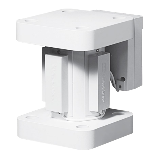
- Page 12 (Anderson-Negele) Shim Junction Box Plastic or Stainless Steel (Anderson-Negele) 4 x Microcell Strain gauge sensor, part of Load Stand II Sun shield, installed by the customer, 8 x Hardened washers mounts under the Junction Box and to 4 x Nuts the bottom flange of the Load Stand.
-
Page 13: Operation And Installation
Junction Box Plastic or Stainless Steel (Anderson-Negele) 4 x Microcell Strain gauge sensor, part of Load Stand II Sun shield, installed by the customer, 8 x Hardened washers mounts under the Junction Box and to 4 x Nuts the bottom flange of the Load Stand. -
Page 14: Electrical Installation
Electrical installation Electrical installation Caution Guidelines Very high voltage is present. Remove power from the unit · The procedure below assumes the conduit/cable tray has before installing, removing or making adjustments. been installed. · Seal all conduit fittings against water entry. Install drain holes at conduit/cable tray lowest elevation(s) to allow General Safety condensation to drain. - Page 15 Male flexible conduit fitting Junction Box (Cover removed for clarity) Sensor cover Sensor cable (Factory wiring) Flexible conduit Load Stand II Transducer Drip loop 3/4" Entry hole 1/2" min. clearance to the ground Typical Sensor Wiring To Indicator Drip Loop...
-
Page 16: Installation Of The Sun Shield
Installation of the sun shield Installation of the sun shield The sun shield reduces sun-induced stresses in the Load Stand sensors and provides additional ® Loosen Junction Box screws; Re-thighten after sun shield protection for the sensors. is installed With the junction box cover off, slightly loosen the screws attaching the junction box to the Slide sun shield behind junction Load Stand. -
Page 17: Calibration
4. Set a voltage range on the DMM that will accommodate a measured range of ±1 volt. If you do not have an Anderson-Negele Test Meter, use a Dig- 5. See Pre-Check Procedures, for details on checking the ital Multimeter (DMM) and the Load Stand II junction box to ®... -
Page 18: Troubleshooting Load Stand
· To reduce head radiation/conduction: a) Insulate vessel. b) Contact Anderson-Negele to discuss adding a high temperature insulating pad. · Top bolts jammed: Jammed top bolts indicate undersized bolt holes on vessel mounting... - Page 19 Troubleshooting Load Stand ® Problem Description Solution Small Amplitude Changes Fluctuations can be caused by dam- 3. Put one DMM lead on W and other lead on or Erratic Fluctuations in aged Load Stand sensor. ® R terminal on TB1 of Load Stand junction ®...
- Page 20 Troubleshooting Load Stand ® Problem Description Solution Small Amplitude Changes Fluctuations in readings can be caused Using a Digital Multimeter (DMM) or ohmmeter, or Erratic Fluctuations in by short to ground. check for shorts to ground as follows: Display Readings 1.
- Page 21 Use a heat shield like a metal plate to reflect heat. c) Contact Anderson-Negele to discuss adding a high temperature insulating pad. · Top bolts jammed—Jammed top bolts indicate undersized bolt holes on vessel mounting...
-
Page 22: Dimensional Drawings
Dimensional drawings Dimensional drawings Load Stand II with Plastic Junction Box (IP-66 / NEMA-4) ® Load Stand II (22,6796 kg / 50,000 lbs shown) Plastic Junction Box (IP-66 / NEMA-4) Load Stand II with Stainless Stell Junction Box (IP-66 / NEMA-4X) ®... - Page 23 Notes...
- Page 24 Notes...
Need help?
Do you have a question about the Load Stand II and is the answer not in the manual?
Questions and answers