Table of Contents
Advertisement
Quick Links
Advertisement
Table of Contents

Related Manuals for ANDERSON-NEGELE IZMAG


Summary of Contents for ANDERSON-NEGELE IZMAG
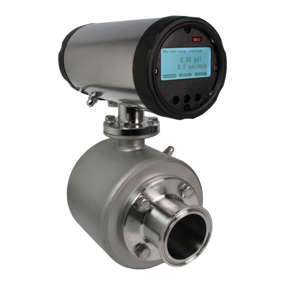
- Page 1 Anderson Instrument Co. Inc. 156 Auriesville Road Instruction Manual Fultonville, NY 12072 1-800-833-0081 Fax 518-922-8997 Instrument Model Number ____________________________ Instrument Serial Number _____________________________ IZMAG Electromagnetic Flow Meter 02070 / 2.21 / 2018-04-17 / BK / NA...
-
Page 3: Table Of Contents
Anderson-Negele 2070-IZMAG Table of contents Table of contents General description ....................5 1.1. Preface ........................5 1.2. Structure and Identification of the device .............. 5 1.3. Function ........................5 1.4. Technical data ......................6 1.4.1. Converter ...................... 6 1.4.2. Transmitter ....................6 1.4.3. - Page 4 4.4.5. Ethernet Communication Option ..............36 Commissioning ....................... 41 5.1. General information ....................41 5.2. Advice for starting-up the IZMAG ................42 5.3. Basic settings upon delivery ................. 42 5.3.1. System structure and operating elements ........... 42 5.4. Flow direction ......................42 5.5.
- Page 5 Anderson-Negele 2070-IZMAG Table of contents 6.9. Image level: Metering parameters ................. 56 6.9.1. LFS ......................57 6.9.2. MSPE ......................57 6.9.3. BSPE ......................57 6.9.4. Average ...................... 57 6.9.5. Offset ......................58 6.9.6. SPAN ......................58 6.9.7. Pipe Detect (recognition of an empty meter tube) ........58 6.9.8.
- Page 6 Anderson-Negele 2070-IZMAG Table of contents 9.5. Spare parts to be kept available on stock ............. 74 10. Decommissioning ....................75 10.1. Temporary decommissioning ................75 10.2. Final decommissioning / disposal ................. 75...
-
Page 7: General Description
Transmitter and converter are two separate pieces Function 1.3. The electromagnetic flow meter, type IZMAG™, measures both the flow rate and the volume of liquid flows at a high precision. The measuring device is suitable for measuring conductive liquids. The IZMAG converter is a microprocessor based device that supplies the transmitter with a switched and regulated coil current. -
Page 8: Technical Data
1.4.1. Converter Supply voltage: IZMAG™ DC: 9 - 32 V DC IZMAG™ AC: 100 - 240 V AC, 50/60 Hz Power consumption: 10 VA max. / 8 watts Electrical fuse connection: AC power supply: T 500 mA DC power supply: T 1.5 A... -
Page 9: General Remarks
Anderson-Negele 2070-IZMAG Transport 1.4.3. Measuring ranges and error limits Flow rate at a Measuring Unit Total measuring range tolerance flow velocity of Size [gal/min ] 1 m/s ± 0.2 % * [ gal/min ] > Gal/min > Gal/min > Gal/min 12.8... - Page 10 Anderson-Negele 2070-IZMAG Transport - The device is operated, serviced, and repaired by sufficiently qualified and authorized personnel only. - The personnel concerned are regularly trained for all applicable questions of the protection of labor and environment and familiarized with the instruction manual and especially the safety precautions included therein.
-
Page 11: General Safety Instructions
Anderson-Negele 2070-IZMAG Transport 1.5.2. General safety instructions These safety instructions must be strictly observed in order: • To not endanger the safety of persons and environment • To avoid any damages to the measuring instrument • To prevent any faulty batches upon the production The electric connection may only be carried out by persons who have the necessary expert knowledge (e.g. -
Page 12: Intended Use
Anderson-Negele 2070-IZMAG Transport Before starting any service and maintenance work, the system has to be flushed with water and emptied. If the flow meter has to be removed from the pipe system, all pipelines will have to be previously emptied and protected by means of some appropriate emptying and shut-off measures. -
Page 13: Special Safety Instructions And Devices
Explanation of the safety symbols used 1.8. The IZMAG™ flow meters are reliable in operation and meet the highest technical specifications. They leave our factory at a safety-related flawless condition. The devices correspond to the relevant standards and directives according to EN 61010 “Electrical safety testing for measurement and laboratory devices”. -
Page 14: Transport
Anderson-Negele 2070-IZMAG Transport Transport General information 2.1. The following points have to be respected in order to avoid damages to the measuring instrument or injuries during the transport of the device: Transport work is only allowed to be carried out:... -
Page 15: Dimensions
Anderson-Negele 2070-IZMAG Transport Dimensions 2.3. 2.3.1. Integral/Remote version - 13 -... - Page 16 Anderson-Negele 2070-IZMAG Transport - 14 -...
-
Page 17: Application
Anderson-Negele 2070-IZMAG Application Application Conditions required for the transmitter 3.1. The transmitter has to be installed in the product line and the converter has to be supplied with voltage. When selecting the place for the installation of the measuring instrument you should in any rate ensure that the housing can be opened for service work whenever desired and that the flow meter can be simply removed, if necessary. -
Page 18: Mounting Position - Electrode Axis
Anderson-Negele 2070-IZMAG Application 3.1.3. Mounting position – electrode axis Due to the principle described, the fitting position – to a certain extent – can be selected any way desired. The basic condition for accurate measuring results is, however, a full and gas- free meter tube. - Page 19 Anderson-Negele 2070-IZMAG Application General Installation Requirements Wrong At the highest point of the pipeline. Gas bubbles accumulate transmitter. incorrect → measurement! Wrong Descending pipe: At the end of the conveyance of the metered product the pipe runs empty. Measuring errors! →...
- Page 20 Anderson-Negele 2070-IZMAG Application Other Installation Considerations Long lines after the flow meter always have to be equipped with a shut-off device. If it is placed before the flow meter, a vacuum will be caused in the metering pipe by the big kinetic energy in the liquid column when shutting off.
-
Page 21: Inlet And Outlet Pipe Sections
Anderson-Negele 2070-IZMAG Application 3.1.4. Inlet and outlet pipe sections For the installation of electromagnetic transmitters DIN 1944 recommends an inlet pipe section of 5 x DN and, accordingly, an outlet pipe section of 3 x DN in case of an undisturbed flow. For an irregular flow (e.g. -
Page 22: Meter Tube Lining
Anderson-Negele 2070-IZMAG Application The transmitter has to be earthed/grounded as shown in this picture. 3.1.8. Meter tube lining A damaged PFA lining can cause faulty measurements or even a failure of the flow meter. Choose the place of installation in such a way that no negative pressure can be caused, even not when the pump is switched off. -
Page 23: Conditions Required For The Converter
Anderson-Negele 2070-IZMAG Application Conditions required for the converter 3.3. In order to guard the converter against damages, always select the place of installation so that: Caution • the ambient temperature is within a range from –20...+55 °C • the field housing is fastened free from any mechanical distortion •... -
Page 24: Installation
Anderson-Negele 2070-IZMAG Operation Installation Only qualified personnel with the authorization of the user are allowed to carry out the installation work. The qualified personnel have to have read and fully understood this instruction manual and follow all instructions given therein. -
Page 25: Installation Instructions For The Converter
This equipment must be connected to a wiring system in accordance with ANSI/NFPA 70, NEC with CSA C22.1, CEC, Part 1 Intended use The flow meter, type IZMAG, is exclusively destined for: - The connection to an earthed/grounded monophase network - The use in industrial areas for reason of EMC... - Page 26 Operation Staff qualification Necessary work to the flow meter, type IZMAG, is only allowed to be performed by trained and qualified personnel in consideration of the relevant regulations for occupational safety. The flow meter has to be correctly connected according to the electrical wiring diagrams.
- Page 27 Anderson-Negele 2070-IZMAG Operation Indicating labels for the AC version Integral Remote Connection of the DC power supply: Positive cable (plus) Negative cable (minus) – Protective conductor Case In case of the DC version the protective conductor has to be connected, too.
-
Page 28: Remote Converter
Anderson-Negele 2070-IZMAG Operation Remote Converter 4.3. Converter The converter is shipped ready for installation. Verify that the converter serial number matches the transmitter serial number as the converter was factory flow tested and calibrated with the accompanying transmitter as a matched set of components Caution- Never operate a transmitter and converter with different serial numbers as the flow meter may malfunction or operate improperly. - Page 29 See figure below and descriptions that follow for details. Plug Each IZMAG transmitter and converter is shipped with plugs and seals at all entry points. Always keep plugs in place in ports which are not used. Cord Grip When properly used, this connection offers high resistance to water intrusion by means of a sealing grommet which is compressed against the outer cable sheath.
- Page 30 Connection Cables The IZMAG is provided with two factory-ready connection cables. The electrode signal cable is a gray, 3-conductor shielded cable and the coil drive cable is a black, 2-conductor shielded cable. The ends of both cables are prepared according to factory specifications and are ready to use. Never substitute or splice these cables as this will adversely affect operation of the meter.
- Page 31 Anderson-Negele 2070-IZMAG Operation Connecting the Transmitter to the Converter Caution Line power must be removed from the converter before the connection cables are installed or disconnected to avoid damaging the converter. If the connection cables are shorted together while power is applied to the converter, the coil drive power supply will be damaged.
- Page 32 Anderson-Negele 2070-IZMAG Operation -30-...
- Page 33 Anderson-Negele 2070-IZMAG Operation To install the connection cables at the meter body end: 1. String or pull gray electrode signal cable and the black coil drive cable from transmitter terminal box to the converter. Pull the excess connection cable to the converter end of the cable run.
-
Page 34: Electrical Connection Of Peripherals
0...20 mA/active, 4...20 mA/active, and 4...20 mA/passive CS3BUS interface (RS485 interface with AndersonCS3-Bus protocol) The measured values of the IZMAG™ are usually put out as volume pulses (pulses per gallon) through a digital pulse output: -32-... - Page 35 Anderson-Negele 2070-IZMAG Operation Integral X200 CS3BUS, data communication Analog output / current output Digital outputs and digital input Connection of the power supply Remote - 33 -...
-
Page 36: Digital Output
Anderson-Negele 2070-IZMAG Operation 4.4.1. Digital output Digital output Hardware Optocoupler, passive Auxiliary voltage 32 V max. Output current 20 mA max. Voltage drop at the optocoupler at 20 mA 0.5…1 V Output frequency 1kHz max. The following figure shows the basic wiring diagram of the pulse outputs. -
Page 37: Digital Input
Anderson-Negele 2070-IZMAG Operation 4.4.2. Digital input Digital input Hardware Optocoupler, passive Auxiliary voltage 9…32 V Input resistance < 3.2 kΩ Input frequency 1kHz max. Function Voltage ON Function active Terminal X3 / No. 32 Plus Terminal X3 / No. 31... -
Page 38: Cs3-Bus
4.4.5. Ethernet Communication Option 4.4.5.1. Description When equipped, the IZMAG flow meter will have an RJ45 connector on the terminal board. This connector offers Ethernet IP communication of key process variables along with the ability to modify parameterization using available web pages. - Page 39 IZMAG display. In this method a webpage will open giving the opportunity to modify the IP address. In addition to the IP address, the IZMAG has a gateway address. This can be found on the same programming tier of the meter display as the IP address and is freely programmable using the meter display.
- Page 40 Anderson-Negele 2070-IZMAG Operation Table 2 Table 3 Input Data Bytes Format Content 0 - 1 WORD Function "measure stop" (see Table 5) 2 - 3 WORD Function "reset quantity" (see Table 6) 4 - 7 REAL (IEEE-754) Free for extension...
- Page 41 Anderson-Negele 2070-IZMAG Operation Table 5 Table 6 - 39 -...
- Page 42 The first 3 Bytes of the IP-address should be the same for both the PC and IZMAG, if the subnet mask is set to "255.255.255.000". Start the browser of the PC and put in the IP-address from the IZMAG (e.g. "http://192.168.000.123/") and press key "ENTER".
-
Page 43: Commissioning
Operation This main page has a series of tabs at the top that mimic the menu options of the IZMAG. The main page also displays the total, flow rate and meter status just as it would on the IZMAG display and continuously updates the page to what the IZMAG is reading. -
Page 44: Advice For Starting-Up The Izmag
5.3.1. System structure and operating elements The electronics are permanently installed in the IZMAG™ converter. The display is arranged on the front above the three optical keys. The electrical connections are on the rear side of the converter. -
Page 45: Zero Point Adjustment ("Zero Adjust")
Metrologically accurate flow measurements are only possible, if the meter tube is completely filled with liquid. In order to avoid an undefined counting in case of an empty meter tube, the IZMAG™ offers both an internal and an external possibility for measurement suppression: 5.7.1. -
Page 46: Metering At Low Conductivities
Metering at low conductivities 5.8. The IZMAG™ is capable of measuring liquids from a minimum conductivity of 5 µS/cm. In order to obtain perfect results even at conductivities of less than 50µS/cm, the internal “EMPTY pipe detection” has to be switched off in the parameters. -
Page 47: Basic Keypad Functions
The basic setting of the image navigator is the measured value level where the volume and the flow rate are displayed. A timeout function makes sure that the IZMAG™ always returns to that image level. -
Page 49: Flowchart
Anderson-Negele 2070-IZMAG Operation Flowchart 6.3. -
Page 50: Zero Reset Of The Volume Counter
Anderson-Negele 2070-IZMAG Operation 6.3.1. Zero reset of the volume counter The main image shows the total. “Zero reset” is a function which can be carried out without any additional activation. For a zero reset, please keep the key depressed for about 5 seconds. -
Page 51: How To Release A Parameter Change
Anderson-Negele 2070-IZMAG Operation The next pulse output mode appears on the display. 6.3.4. How to release a parameter change: If a parameter has to be changed and the parameter change is open for change, the display will request the input of the code number. -
Page 52: Image Level: Measured Values
Anderson-Negele 2070-IZMAG Operation Image level: Measured values 6.4. 6.4.1. Measured value: Volume A 4-seconds long activation of the key will reset the volume to “0”. The size of the digits is controlled by the size of the measured value. The volume indication is the central image that is always shown after a reset. -
Page 53: Language
Anderson-Negele 2070-IZMAG Operation 6.5.1. Language Use the key for changing the language. You might be prompted to first input an unlock code. 6.5.2. CS3Bus address The CS3-Bus address can be changed by means of the key You might be prompted to first input an unlock code. -
Page 54: Profibus Address
Anderson-Negele 2070-IZMAG Operation 6.5.4. Profibus address The profibus address can be adjusted by means of the key. 6.5.5. Parameter Mode The Parameter Mode can be changed by means of the key Mode 0 Meter unlocked Mode 1 Parameter locked until code entry... - Page 55 Anderson-Negele 2070-IZMAG Operation Mode1 2 independent channels (IMP1 and IMP2) with different values (pv1 and pv2) Pulse output independent of the flow direction. Maximum pulse length of tp1 and tp2 in ms 0 ms = pulse-to-pause ratio 1:1. Maximum frequency: 1000 Hz.
-
Page 56: Pv1
Anderson-Negele 2070-IZMAG Operation 6.6.2. PV1 The pulse value PV1 can be changed by the key. PV1 is valid for Mode1, Mode 5, Mode7 and Mode6. You might be prompted to first input an unlock code. 6.6.3. TP1 Use the key to change the pulse length of TP1 to ms. -
Page 57: Image Level: Digital Input
Anderson-Negele 2070-IZMAG Operation Image level: Digital input 6.7. The settings for the digital input are made on this image level. The main image shows the current device setting. 6.7.1. Function: Digital input The function of the digital input can be selected by means of key The input can be set to: •... -
Page 58: Current Output Mode
Anderson-Negele 2070-IZMAG Operation 6.8.1. Current output mode By this key you can change the mode for the current output. You can choose among 3 different modes: 4 – 20 mA active 4 – 20 mA passive 0 – 20 mA active Active / passive - see analog output. -
Page 59: Lfs
Anderson-Negele 2070-IZMAG Operation 6.9.1. LFS The key can be used to change the low-flow suppression LFS in %. The low-flow volume is calculated from the Qmax value. You might be prompted to first input an unlock code. 6.9.2. MSPE By means of the key you can change the dimensionless factor MSPE. -
Page 60: Offset
Anderson-Negele 2070-IZMAG Operation 6.9.5. Offset Press the key for changing the Offset value. The Offset is a calibration value of the sensor which is normally not changed! You might be prompted to first input an unlock code. 6.9.6. SPAN The SPAN value can be changed by the aid of the key. -
Page 61: Image Level: Special Functions
The meter tube has to be filled up with the liquid to be measured. No flow rate is allowed to be available, the liquid rests. Unless the prerequisites are observed, a faulty ZERO value will be determined and the IZMAG™ will not be able work correctly. Important information 6.10.2. -
Page 62: Error Register: Metering
Anderson-Negele 2070-IZMAG Operation 6.11.1. Error register: Metering This image shows the error numbers of the measurement. The error number is reset while the flow meter is set back to zero. 6.11.2. Error register: Operating system This image shows the error numbers of the operating system. -
Page 63: Simulation Of The Flow Rate
6.11.5. Simulation of the flow rate This function can simulate the complete metrological functionality of the IZMAG™ converter, i.e. the pulse outputs and the current output behave like in the normal operation. This function is suitable for the “dry” commissioning of a system or of system sections. -
Page 64: Parameterization
2070-IZMAG Parameterization At the factory the IZMAG™ is provided with standard parameters (factory settings). Only trained persons authorized by the user of the flow meter are allowed to set and/or change parameters. The persons concerned have to be familiar with the process sequence. - Page 65 Anderson-Negele 2070-IZMAG Troubleshooting Table of the abbreviations used and their meaning: Abbreviation Function IMP1 Pulse output 1 IMP2 Pulse output 2 IMP3 Pulse output 3 Digital input 1 Pulse value for IMP1 Pulse length for IMP1 Pulse value for IMP2...
-
Page 66: Adjustments
Anderson-Negele 2070-IZMAG Adjustments 7.1. The IZMAG™ normally needs no adjustment. Usually, the zero point adjustment (“ZERO adjust”) is carried out during the first commissioning only. If, however, some deviations have to be compensated which were determined e.g. upon a comparison with a calibration vessel or a balance it is possible to make an adjustment via the factor “m spe”. -
Page 67: Measuring Accuracy
The transmitter is positioned in the centre of the pipeline. Troubleshooting Error diagnosis 8.1. The IZMAG™ is equipped with an integrated self-monitoring function. Malfunctions are recognized and automatically removed, if necessary. 8.1.1. Error diagnosis via the display Displayed messages can support the troubleshooting in case of malfunction or faulty measurement. -
Page 68: Error List
Anderson-Negele 2070-IZMAG Error message for the measurement Error message for the operating system Usually, all displayed messages are erased when the volume is reset to zero. In case of a permanent malfunction, however, the message will be reactivated over and over again. -
Page 69: Typical Effects Or Error Sources
(hardware or software) for your further diagnosis of the digital or analog output! 8.2.2. No pulse transmission despite displayed flow (a) Check the electric circuit (the IZMAG™ outputs have to be supplied by an auxiliary voltage of 24 V DC)! -
Page 70: Deviations Of Measured Values
Anderson-Negele 2070-IZMAG If the differences only occur after the disconnection of the external evaluating device, it should be checked: If the burden of the whole current loop is higher than 500 Ω? (Observe the technical data sheets of the connected devices!) If the input of the external evaluating device is erroneously designed as an “active”... -
Page 71: Error Reset
Anderson-Negele 2070-IZMAG Troubleshooting h) Check the reference measuring methods or the test procedure (reference meter such as a balance): • Take into account the temperature compensation of the volume. • If different products are compared with the value of the balance, the conversion will have to be carried out by means of the density. -
Page 72: Maintenance
• Rinse the pipe system with clear water before the disassembly of fittings or instruments in order to remove possible residuals of chemicals! Routine maintenance 9.2. On normal operating conditions the flow meter type IZMAG™ does not require any special maintenance work. Nevertheless, we wish to give you some recommendations for maintenance steps: Cleaning Deposits in the meter tube or at the electrodes will cause measuring errors or malfunctions. -
Page 73: Preventive Maintenance Steps
• Not to reduce the service life of the system and its components The preventive maintenance steps for the flow meter type IZMAG™ refer to the seals of the pipe connections. The recommended maintenance intervals result from the experience in other systems. -
Page 74: Repairs
Anderson-Negele 2070-IZMAG Anderson recommends checking the measuring spot continuously, i.e.: The operators of the system should currently pay attention to: • occurring leaks • unusual measuring results Regular maintenance: The following are suggestions for determining a maintenance schedule: A replacement of all seals and wearing parts in regular intervals, e.g. every year. -
Page 75: Special Program Functions
Moreover, it is possible to use those functions for the adjustment and verification of connected devices. 9.4.1. Flow simulation As an adjusting aid or for diagnosing purposes of connected devices the IZMAG offers the possibility to simulate flow without any flowing product. -
Page 76: Simulation Via The Display Unit
Anderson-Negele 2070-IZMAG 9.4.2. Simulation via the display unit Select the “SIMULATION” function by means of the keypad. During the simulation the analog output is set to 12.0 mA (4...20 mA setting) or 10.0 mA (0...20mA setting). The volume pulses are produced for the flow of 50 % according to the set pulse value. -
Page 77: Decommissioning
Anderson-Negele 2070-IZMAG Decommissioning Temporary decommissioning 10.1. Should the device be put out of operation for a temporary period only, no special measures have to be observed for its later recommissioning. If the transmitter is removed out of the process line, the pipe system first has to be emptied and depressurized. - Page 78 Anderson-Negele 2070-IZMAG...
- Page 79 Anderson-Negele 2070-IZMAG...
- Page 80 Anderson-Negele 2070-IZMAG Warranty and Return Statement These products are sold by The Anderson Instrument Company (Anderson) under the warranties set forth in the following paragraphs. Such warranties are extended only with respect to a purchase of these products, as new merchandise, directly from Anderson or from an Anderson distributor, representative or reseller, and are extended only to the first buyer thereof who purchases them other than for the purpose of resale.
- Page 81 Anderson-Negele 2070-IZMAG...
- Page 82 Anderson-Negele 2070-IZMAG ANDERSON INSTRUMENT CO., INC • 156 AURIESVILLE RD. • FULTONVILLE, NY 12072 • USA • 800-833-0081 • FAX 518-922-8997 ANDERSON INSTRUMENT CO. LP • 400 BRITANNIA RD. EAST, UNIT 1 • MISSISSAUGA, ONTARIO L4Z 1X9 • CANADA • 905-603-4358 • FAX 905-568-1652 NEGELE MESSTECHNIK GmbH (A Division of Anderson) •...
Need help?
Do you have a question about the IZMAG and is the answer not in the manual?
Questions and answers