
Subscribe to Our Youtube Channel
Related Manuals for ANDERSON-NEGELE FMQ


Summary of Contents for ANDERSON-NEGELE FMQ
- Page 1 SENSORS FOR FOOD AND LIFE SCIENCES. INSTRUCTION MANUAL Electromagnetic Flow Meter 30008 / 1.3 / 2021-05-17 / BK / NA...
-
Page 3: Table Of Contents
Table of contents Table of contents General description ....................1 1.1. Preface ........................1 1.2. Function ........................1 1.3. Technical data ......................2 Converter ...................... 2 Transmitter ....................2 1.3.3. Measuring ranges ..................3 Safety instructions ....................4 2.1. General remarks ....................... 4 Special attention to the user ................. - Page 4 Display ........................22 Commissioning ....................... 24 6.1. General information ....................24 6.2. Advice for starting-up the FMQ ................25 6.3. Basic settings upon delivery ................. 25 System structure and operating elements ........... 25 6.4. Zero point adjustment (“ZERO adjust”) ..............26 6.5.
- Page 5 Table of contents Offset ......................39 SPAN ......................39 Pipe Detect (recognition of an empty meter tube) ........39 Nominal width ..................... 39 7.8. Display level: Special functions ................39 Zero adjust....................40 Factory settings ..................40 LCD contrast ....................40 7.9.
- Page 6 Table of contents Simulation via the display unit ..............57 10.5. Spare parts ......................58 11. Decommissioning ....................61 11.1. Temporary decommissioning ................61 11.2. Final decommissioning / disposal ................. 61...
-
Page 7: General Description
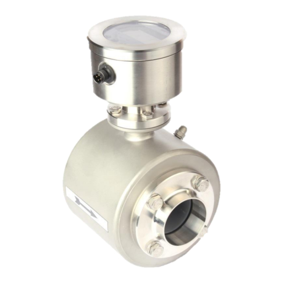
1.2. Function The electromagnetic flow meter, type FMQ, measures both the flow rate and the volume of liquid flows at a high precision. The measuring device is suitable for measuring conductive liquids. The FMQ converter is microprocessor controlled. It supplies the transmitter with a switched and regulated coil current. -
Page 8: Technical Data
General description 1.3. Technical data Converter Supply voltage: FMQ DC: 24V ±10% DC Power consumption: 4 watts max. Electrical fuse connection: DC power supply: T 1A Digital pulse output/IO-Link: 1 x optocoupler output Maximum load: 32 V / 20 mA / pulse sequence: 1 kHz max. -
Page 9: 1.3.3. Measuring Ranges
General description 1.3.3. Measuring ranges Flow rate at a Unit Total flow range Flow velocity of 1 m/s [ L/h ] [ L ] 3,000 7,000 18,000 1,800 30,000 3,000 45,000 4,500 70,000 7,000 1,200 120,000 12,000 1,800 180,000 18,000 2,800 280,000 28,000... -
Page 10: Safety Instructions
- All the safety and warning instructions attached to the flow meter are not removed and kept in a legible condition. In case of problems that cannot be solved, the user of the system should contact the service department of Anderson-Negele. -
Page 11: General Safety Instructions
Arrangement General safety instructions These safety instructions have to be strictly observed in order: • To not endanger the safety of persons and environment • To avoid any damages to the flow meter • To prevent any faulty batches upon the production The electric connection may only be carried out by persons who have the necessary expertise (e.g. -
Page 12: Intended Use
Anderson-Negele. Possible misuse Any use being in contradiction to the above-mentioned application indicates a misuse of the flow meter! In such a case Anderson-Negele does not assume any responsibility for the safety. -
Page 13: Special Safety Instructions And Devices
Arrangement 2.3. Special safety instructions and devices The following dangers could be directly or indirectly caused by the flow meter, type FMQ, during operation or commissioning: • Electric shock if the electronic housing is opened improperly • Burns by touching hot pipe sections •... -
Page 14: Transport
Arrangement Transport 3.1. General information The following points have to be followed in order to avoid damages to the flow meter or injuries during the transport of the device: Transport work is only allowed to be carried out: - By accordingly qualified and authorized persons - By the aid of appropriate lifting and mounting devices - On the condition that any risk can be fully excluded while the device is lifted or conveyed... -
Page 15: Dimensions And Weight
Arrangement 3.3. Dimensions and weight Compact version Weight [mm] [mm] [mm] [mm] [mm] [kg] 11.2 13.2... -
Page 16: Dimensions Of The Process Connections
Arrangement Dimensions of the process connections The welding socket belongs to the standard delivery. If a flow meter of the previous series IZM-S™ or IZM-L™ is replaced by a FMQ, adapters up to DN 100 are required. Welding socket (standard) -
Page 17: Air And Gas
Arrangement Air and gas The electromagnetic flow meter can supply good measuring results in the measurement of gas- free liquids only. Air locks or deaeration in a liquid will lead to incorrect measurements. Thus, make sure that air locks or other possible parts of gas are safely separated before the measuring device e.g. -
Page 18: Fitting Position - Electrode Axis
Arrangement Fitting position – electrode axis Due to the principle described, the fitting position – to a certain extent – can be selected any way desired. The basic condition for accurate measuring results is, however, a full and gas-free meter tube. - Page 19 Arrangement Suggestions for installation Wrong At the highest point of the pipeline. Gas bubbles → accumulate in the transmitter. Faulty measurement! Wrong Descending pipe: At the end of the conveyance of the metered product → the pipe runs empty. Measuring errors! f reier Auslauf Correct Free outlet...
- Page 20 Arrangement Keep the recommended inlet and outlet sections! 5xD N 3xD N Avoid curvatures of space before the flow meter! Installation requirements for 3-A sanitary applications Correct In horizontal applications a slope of greater than 5 degrees is required to ensure that proper drainage occurs in the pipeline.
-
Page 21: Conductivity Conditions
Arrangement Inlet and outlet pipe sections For the installation of electromagnetic transmitters DIN 1944 recommends an inlet pipe section of 5 x DN and, accordingly, an outlet pipe section of 3 x DN in case of an undisturbed flow. For an irregular flow (e.g. -
Page 22: Meter Tube Lining
4.2. Flow direction The FMQ measures the flows in both flow directions in principle. The main flow direction is marked on the transmitter by means of an arrow: In the standard setting the digital outputs emit the volume pulses independently of the flow direction. -
Page 23: Alignment Of The Converter
(e.g. welding distortion) is kept limited to the absolute minimum. Before welding work is started, the FMQ will have to be removed from the pipeline: Fasten the FMQ transmitter by some welding point inside the pipeline! -
Page 24: Cover
If the cover is closed (finger-tight), the flow meter will be protected from moisture! The FMQ is only protected from moisture, if the covers are correctly screwed down. A properly screwed down cover is recognized by the fact that the metallic stop is reached. -
Page 25: Installation
Installation Installation Only qualified persons with authorization of the user are allowed to carry out the installation work. The qualified personnel have to have read and fully understood this instruction manual and follow all instructions given therein. The current standards will establish the requirements for the execution of the installation. The following points should be taken into account after completion of the installation work: •... -
Page 26: Installation Instructions For The Converter
5.2. Installation instructions for the converter As the FMQ is a compact design, the converter is arranged on the transmitter, i.e. it is located straight on the pipeline. When installing the flow meter, pay special attention to the fact that no moisture by drip or splash water can get onto the electronic board. - Page 27 Installation DC Input M12-plug connection: 4-pin version 5-pin version M12-plug, 4-pins DC Supply + (24V) 4…20 mA Output DC Supply - (0V / GND) Pulse Output / IO-Link (optional) M12-plug, 5-pins DC Supply + (24V) 4…20 mA Output DC Supply - (0V / GND) Pulse Output / IO-Link (optional) DC Input + (9…24V) Digital output...
-
Page 28: Digital Output
Installation Analog output - current output Analog output Hardware mode Active Operating mode 4...20 mA 500 Ω max. Load Error < 0.2 % The analog output works in both flow directions! Figure 1: Wiring diagram – digital output and active current output 5.2.4 Optional Digital Input Digital input Hardware... - Page 29 Installation 57002A0001 Display Cap Conversion instructions: Unscrew the cover! Connect the display and the converter (plug XD1) by the cable! 3. Fix the display by the M3x10 screws 4. Close the housing by the cover (with the transparent pane)!
-
Page 30: Commissioning
Commissioning Commissioning 6.1. General information The measuring device may only be operated by trained persons who have the necessary authorization from the user of the device. The operators have to be familiar with the process sequence, able to recognize possible dangers, and in a position to take the necessary steps for the removal of accident risks. -
Page 31: Advice For Starting-Up The Fmq
System structure and operating elements The electronic part is permanently installed in the FMQ converter. The electrical connection (M12 plug) is on the side of the device. For units not equipped with the optional display a satin-glass pane with a 3-coloured background LED-lighting is provided for meter status. The color shows the current status of the device. -
Page 32: Zero Point Adjustment ("Zero Adjust")
Metering with an empty meter tube Metrologically correct flow measurements are only possible if the flow meter is filled with liquid. In order to avoid erroneous flow measurement due to an empty meter tube, the FMQ offers automatic detection and shut down for this condition.n: "EMPTY pipe detection"... -
Page 33: Status Indication
6.7. Optical operating elements (optional display version) The display unit is provided with optical keys for the operation which enable the FMQ to be operated through the closed cover. The converter calibrates the optical keys in regular intervals. Such a calibration can only function perfectly, if the optical keys are not covered. -
Page 34: Operation
Operation Operation Only trained persons with the authorization of the user are allowed to operate the FMQ. During normal measurements the display operation is restricted to the zero reset of the volume registers. The keypad is dynamically controlled by the image navigator. -
Page 35: Basic Keypad Functions
The basic setting of the display navigator is the measurment display where the volume and the flow rate are displayed. A timeout function makes sure that the FMQ always returns to that display level. - Page 36 Operation Display navigator Main level Sub-levels BE1S1 BE1S2 BE1S3 Measured value Measured value Flow rate Total volume Volume Flow rate Volume BE2S1 BE2S2 BE2S3 BE2S5 Basic parameters Language CS3-Bus Dimensions Q type Device settings BE3S2 BE3S3 Pulse output Device settings BE5S2 BE5S3 Current output...
-
Page 37: Zero Reset Of The Volume Counter
Operation Zero reset of the volume counter The main display shows the volume. This image is permanently shown while the flow meter is switched on. “Zero reset” is a function which can be carried out without any additional activation. For a zero reset, please keep the key depressed for about 5 seconds. -
Page 38: How To Release A Parameter Change
Operation The current “Dimension” is set to “Litres”. The next “Dimension” is selected and/or adjusted by means of the key. The next “Dimension” appears on the display. How to release a parameter change: If a parameter has to be changed and the parameter change is not unlocked, the display will request the input of the code number. -
Page 39: Display Level: Measured Values
Operation 7.3. Display level: Measured values This level consists of the pictures BE1, BE1S1, BE1S2, and BE1S3. Measured value: Volume key will reset the volume to “0”. A 4-seconds long activation of the The size of the digits is controlled by the size of the measured value. The volume indication is the central image that is always shown after a reset. -
Page 40: Error Message: Transmitter Not Connected
Operation The totalizer cannot be reset to zero. Error message: Transmitter not connected This error message will be displayed, if the transmitter is not connected. The cause of the error is the missing coil connection. 7.4. Display level: Base parameters This level consists of the following pictures: BE2, BE2S1, BE2S2, BE2S3, BE2S4 and BE2S5. -
Page 41: Dimension
Operation Dimension key can be used for changing the dimension (unit) of the measured value. You could be asked in advance to enter the unlock code. When changing the dimension of the meter the single and total amounts will be set back on zero. Abbreviation Unit m dim... -
Page 42: Display Level: Pulse Output
Operation 7.5. Display level: Pulse output This level consists of the pictures: BE3, BE3S1, BE3S2, and BE3S3. This level serves for the setting of the pulse output. The main level shows the current device setting. The pulse value PV1 can be changed by the key. -
Page 43: Display Level: Current Output
Operation 7.6. Display level: Current output This level consists of the pictures BE5, BE5S2, and BE5S3. On this level the settings for the current output are made. The main level shows the current setting of the device. Qmax The key can be activated for changing the Qmax value for the current output. -
Page 44: Lfs
Operation The key can be used to change the low-flow suppression LFS in %. The low-flow volume is calculated from the Qmax value. Lock code if required “222”. MSPE By means of the key you can change the multiplier MSPE. Lock code if required “222”. -
Page 45: Offset
Operation Offset Press the key for changing the Offset value. The Offset is a calibration value of the sensor which is normally not changed! Lock code if required “145”. SPAN The SPAN value can be changed by the aid of the key. -
Page 46: Zero Adjust
The meter tube has to be filled up with the liquid to be measured. No flow rate is allowed to be available, the liquid rests. Unless the prerequisites are observed, a faulty ZERO value will be determined and the FMQ will not be able work correctly. Important information Factory settings All parameters are reset to the factory settings. -
Page 47: Display Level: Service Level
Operation 7.9. Display level: Service level This level consists of the pictures BE8, BE8S1, BE8S2, BE8S3, and BE8S4, BE8S5. Only service values are displayed and service functions are performed on this service level. Error register: Metering This shows the error numbers of the measurement. The error number is reset while the flow meter is set back to zero. -
Page 48: Simulation Of The Pulse Outputs
Lock code if required “333”. Simulation of the flow rate This function can simulate the complete metrological functionality of the FMQ converter, such as the pulse outputs and the current output behave like in the normal operation. This function is suitable for the “dry”... -
Page 49: 7.10. Display Level: Info
Unless the device is equipped with a parameter box, the text “no parameter box” will be displayed. If the text “SENSORBOX” is displayed, the memory box is specific for the FMQ. If the text “MEMBOX” is displayed, the box included in the converter has been taken from the previous... -
Page 50: 7.11. Lock Switch
Operation 7.11. LOCK switch From the software version V2.02 it is possible to deactivate the optical keys by means of the LOCK switch (left-hand switch position) in order to avoid operating errors. The display level (BE1, BE1S1, BE1S2 or BE1S3) that will be shown during the locked period will depend on what the display indicated at the time of locking. -
Page 51: Parameterization
Parameterization Parameterization At the factory the FMQ is provided with standard calibration and configuration parameters (factory settings). Only trained individuals authorized by the user of the flow meter should be allowed to set and/or change parameters. These individuals need to be familiar with the... - Page 52 Parameterization Q max [ l/h ] PV1 [ pulse/l ] 3000.0 1000.0 7000.0 100.0 18000.0 100.0 30000.0 100.0 45000.0 10.0 70000.0 10.0 120000.0 10.0 180000.0 10.0 280000.0 10.0 Table of the abbreviations used and their meaning: Abbreviation Function Pulse value for IMP1 Pulse length for IMP1 Pulse length for IN1 Q max.
-
Page 53: Adjustments
Parameterization 8.1. Adjustments The FMQ normally needs no calibration adjustment. Usually, the zero point adjustment (“ZERO adjust”) is carried out only during the first commissioning. If, however, some deviations have to be compensated for which were determined when comparing with a calibration vessel or a balance it is possible to make an adjustment using the “m spe”... -
Page 54: Measuring Accuracy
Parameterization An example is shown overleaf: Example: Deviation F of +0.54% determined during a comparative measurement Calibration vessel: = 5000 L Display: = 5027 L 5000 • 1.0 = 0.9946 _______ m spe = 5027 This would mean that we would set the m spe value to 0.9946 8.2. -
Page 55: Trouble-Shooting
Trouble-shooting Trouble-shooting 9.1. Error diagnosis The FMQ is equipped with an integrated self-diagnostic system. Malfunctions are recognized and automatically removed, if necessary. Error diagnosis via the display Displayed messages can support the troubleshooting in case of malfunction or faulty measurement. A distinction is made between error messages for the measurement or for the operating system. -
Page 56: Error List
Trouble-shooting Error list Error Diagnosis Remedial actions No.: a. The measuring result can be falsified due to the interference received. - Reset the message by resetting the individual quantity to zero! b. Check the whole installation for possible EMC Error found on the occasion of the internal interference sources;... -
Page 57: Typical Effects Or Error Sources
FMQ. The analog output signal then should be checked by using the simulating function on the meter and an ammeter: - If the analog output is ZERO at a 50% simulation, the FMQ electronics are defective making replacement of the converter required. -
Page 58: Deviations Of Measured Values
Trouble-shooting If the problem only occurs when the external device is connected then the following should be checked: If the burden of the whole current loop is higher than 500 Ω? (Observe the technical data sheets of the connected devices!) If the input of the external evaluating device is incorrectly configured for a passive input? Faults can especially occur upon a connection to a PLC due to the fact that it might... -
Page 59: Error Reset
Trouble-shooting Check the reference measuring methods or the test procedure (reference meter such as a scale): • Take into account the temperature compensation of the volume. • If different products are compared with the value of the scale, a conversion will need to be made for the change in density. -
Page 60: Maintenance
Maintenance Maintenance 10.1. Safety instructions for maintenance work Maintenance and repair work must only be carried out by skilled personnel with the authorization from the user. The persons involved need to be familiar with the process sequence and be able to recognize possible dangers and to take all necessary steps to remove imminent risks of accidents. -
Page 61: 10.2. Routine Maintenance
• To improve the service life of the system and its components The preventive maintenance steps for the flow meter type FMQ refer to the seals of the pipe connections. Recommended maintenance intervals are a result of the experience in other systems. However,... -
Page 62: 10.3. Repairs
Accuracy tests of the flow meters of the system in regular intervals in the frame of the in- house quality/metrology standards. Of course, the aforesaid regular maintenance work can be carried out by the specialists of the Anderson-Negele service department, if preferred. -
Page 63: Repair Work
It is also possible to use those functions for the adjustment and verification of connected devices. Flow simulation As an adjusting aid or for diagnosing purposes of connected devices the FMQ offers the possibility to simulate flow without any flowing product. Simulation via the display unit Select the “SIMULATION”... -
Page 64: 10.5. Spare Parts
Maintenance 10.5. Spare parts The spare parts list results from the experience in the different applications of the flow meter. However, the actually required spare parts may be deviating from it for the following reasons: • Daily running time and number of the annual production days •... - Page 65 Maintenance...
- Page 66 SS Blind Cap 44887A0001 WINDOW ITM 36241N0017807900 79MM O-RING 56623D0004 RCPT MACH EURO TO M16 56623D0006 ASY RCPT 4CNDT IOLINK FMQ SP56623D0005 44401E3199 M3 x 3mm x 5mm MALE MALE STANDOFF 42068A0001 HEAT SINK FMQ FMQ-EL-DC-BOC1 FMQ ELECTRONICS 1 44401E2108...
-
Page 67: Decommissioning
Decommissioning 11.1. Temporary decommissioning If the device is to be put out of operation for a temporary period only, no special measures have to be observed for its later recommissioning. If the transmitter is removed from the process line, the pipe system first has to be emptied and depressurized. - Page 68 Maintenance Anderson Instrument Company Inc. | 156 Auriesville Road | Fultonville, NY 12072 | Phone: 518-922-5315 | Fax: 518-922-8997 Negele Messtechnik GmbH | Raiffeisenweg 7 | 87743 Egg an der Guenz | Germany | Phone: +49 (0) 83 33 . 92 04 – 0 | Fax: +49 (0) 83 33 . 92 04 - 49...
Need help?
Do you have a question about the FMQ and is the answer not in the manual?
Questions and answers